DOE-based systems and devices for producing laser beams having modified beam characteristics

Inactive Publication Date: 2002-10-31
METROLOGIC INSTR
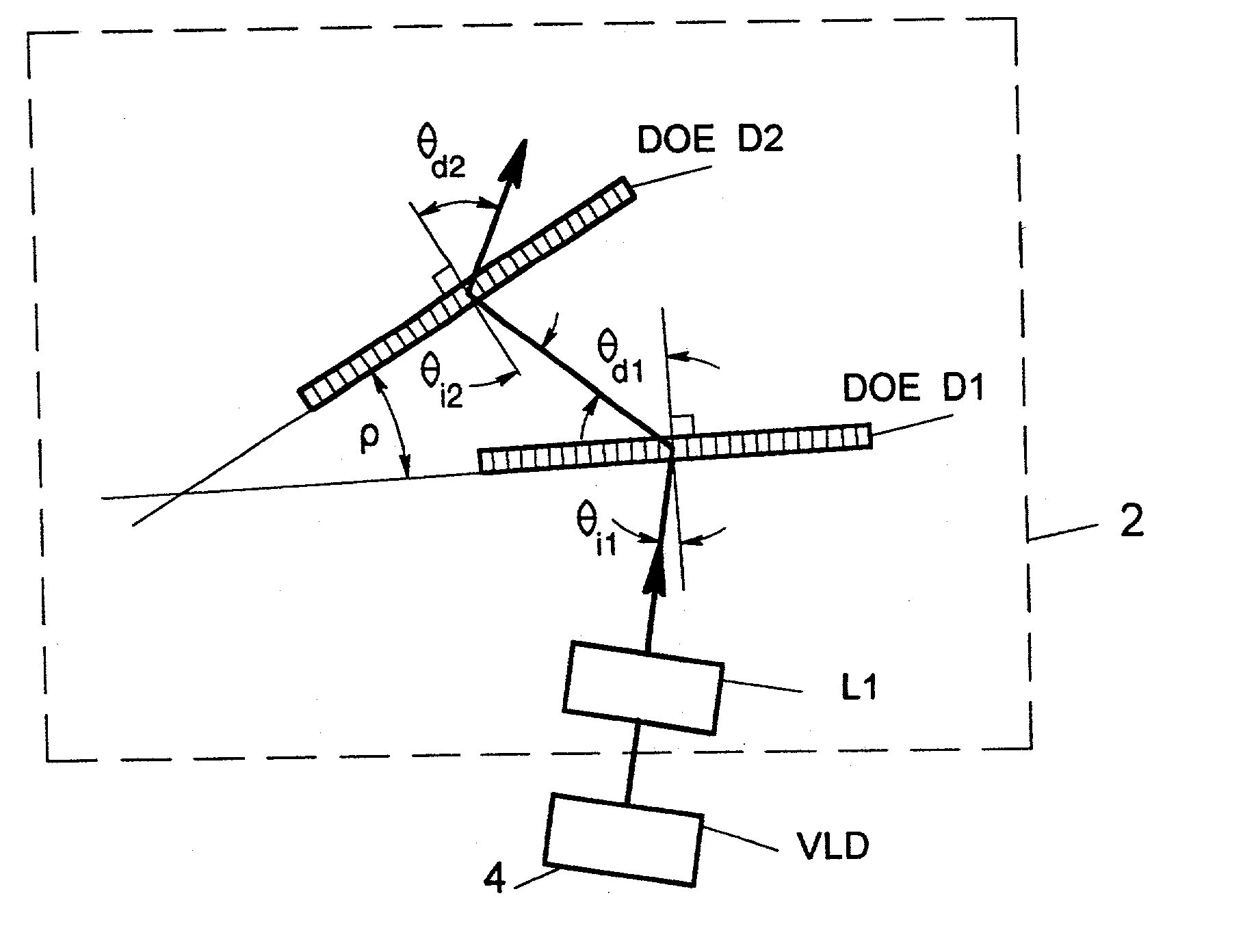
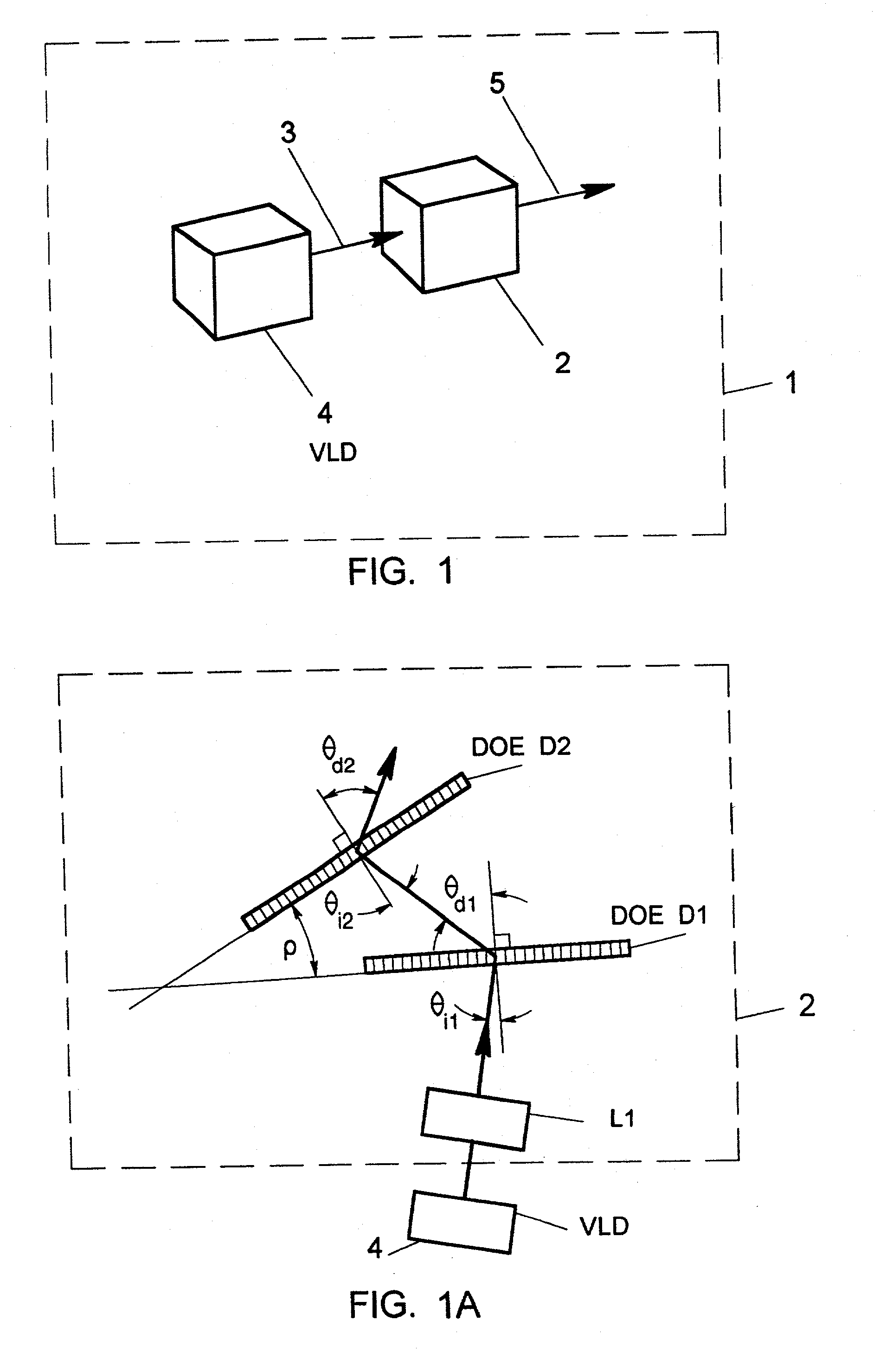
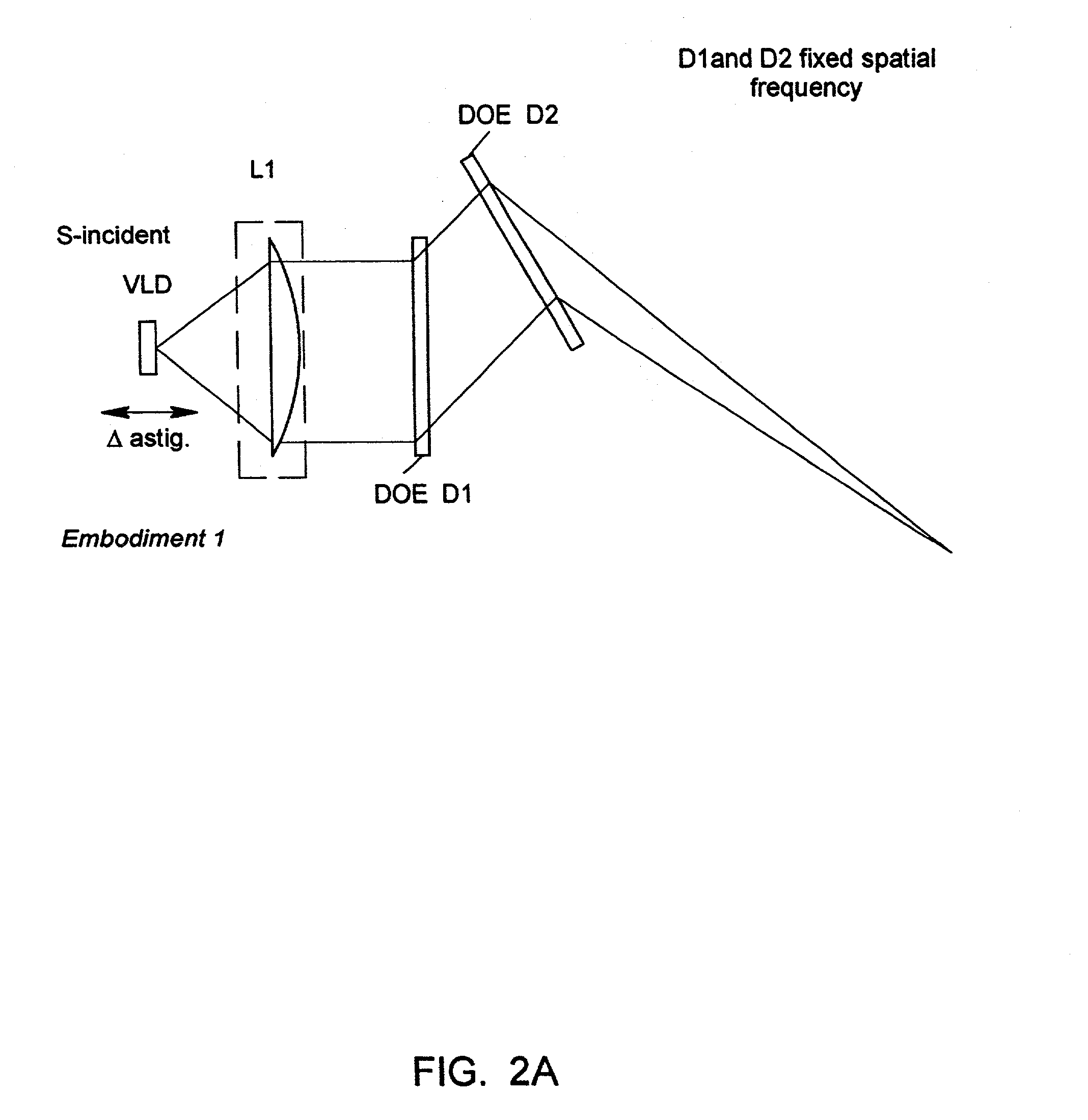
View PDF10 Cites 46 Cited by
  • Summary
  • Abstract
  • Description
  • Claims
  • Application Information

AI Technical Summary

Benefits of technology

0013] Thus, it is a primary object of the present invention to provide an improved method of designing optical systems for modifying the inherent elliptical

Problems solved by technology

While laser diodes offer significant advantages over other laser sources, e.g. gas lasers, in terms of efficiency, size, and cost, they nevertheless suffer from several undesirable optical characteristics, namely: high beam divergence, elliptical beam profile, and astigmatism.
While complex refractive-optics type systems (employing anamorphic lenses and the like) have been developed for the purpose of correc

Method used


Image

  • DOE-based systems and devices for producing laser beams having modified beam characteristics
  • DOE-based systems and devices for producing laser beams having modified beam characteristics
  • DOE-based systems and devices for producing laser beams having modified beam characteristics

Examples


case 1

[0304] Constructing Fixed Frequency HOEs

[0305] When constructing a fixed frequency hologram (HOE), the object and reference beams must have the same radius of curvature. In most applications, this is accomplished by collimating the two beams so that we have two wavefronts at the hologram recording medium. The angle between the two beams will determine the spatial frequency of the fixed frequency hologram. The greater the angle, the greater the spatial frequency. The actual spatial frequency of the hologram is, more precisely, a function of the angles of incidence of the two beams at the hologram recording medium and the wavelength of the two beams. The spatial frequency is established by the well known grating equation: d=wavelength / (sinO+sinR), where O is the angle of incidence of the object beam and R is the angle of incidence of the reference beam.

case ii

[0306] Constructing Variable Frequency HOEs

[0307] When constructing a variable frequency hologram (HOE), the object and reference beams must have different radii of curvature. In most applications, this is accomplished by collimating one of the beams and making the other beam a diverging beam. We will choose to call the collimated beam the reference beam. The diverging beam, which we will choose to call the object beam, is generally created by transmitting the object beam portion of the laser beam through a positive lens, such as a microscope objective. The focal point of the converging beam leaving the positive lens then becomes the center of curvature of the object beam. If this positive lens is a spherical lens, the object beam wavefront at the hologram recording medium will be spherical. If the lens is cylindrical lens, with optical power in only one dimension, the object beam wavefront at the hologram recording medium will be cylindrical. In the case of cylindrical wavefront, ...


PUM


Abstract

Novel methods are disclosed for designing and constructing miniature optical systems and devices employing light diffractive optical elements (DOEs) for modifying the size and shape of laser beams produced from a commercial-grade laser diodes, over an extended range hitherto unachievable using conventional techniques. The systems and devices of the present invention have uses in a wide range of applications, including laser scanning, optical-based information storage, medical and analytical instrumentation, and the like. In the illustrative embodiments, various techniques are disclosed for implementing the DOEs as holographic optical elements (HOEs), computer-generated holograms (CGHs), as well as other diffractive optical elements.

Description

RELATED CASES[0001] The present Application is a Continuation of application Ser. No. 09 / 071,512 filed May 1, 1998, which relates to: application Ser. No. 08 / 573,949 filed Dec. 18, 1995; application Ser. No. 08 / 726,522 filed Oct. 7, 1995; application Ser. No. 08 / 886,806 filed Apr. 22, 1997, application Ser. No. 08 / 854,832 filed May 12, 1997; and application Ser. No. 08 / 949,915 filed Oct. 14, 1997; each said Application being commonly owned by Metrologic Instruments, Inc. of Blackwood, N.J., and incorporated herein by reference in its entirety.[0002] 1. Field of Invention[0003] The present invention relates generally to diffractive optical element (DOE) based optical systems of ultra-compact design capable of modifying the inherent elliptical, divergent, eccentric and astigmatic characteristics of laser beams produced from laser diode sources, such as visible laser diodes (VLDs).[0004] 2. Brief Description of the Prior Art[0005] Laser diodes or visible laser diodes (VLD) are often us...

Claims


Application Information

Patent Timeline
IPC IPC(8): G02B5/18G02B5/32G02B26/10G02B27/09G06K7/10G06K7/14G06K17/00G07G1/00H01S5/00H01S5/40
CPCG02B5/1842G02B19/0014G02B26/106G02B27/09G02B27/0944G06K7/10G06K7/10564G06K7/10584G06K7/10594G06K7/10603G06K7/10663G06K7/10673G06K7/10693G06K7/10702G06K7/10792G06K7/10801G06K7/10811G06K7/10851G06K7/10861G06K7/10871G06K7/10881G06K7/10891G06K7/109G06K7/14G06K17/0022G06K2207/1013G07G1/0054H01S5/005H01S5/4025G02B19/0052G02B5/32
Inventor DICKSON, LEROYGOOD, TIMOTHY A.AMUNDSEN, THOMAS C.GROOT, JOHNKNOWLES, C. HARRYCARULLO, THOMAS
Owner METROLOGIC INSTR
Why Eureka
Try Eureka