
Flexible and low cost wavelength management for optical networking

a wavelength management and optical networking technology, applied in the field of flexible and low cost wavelength management for optical networking, can solve the problems of overloading the receiver, different transmission losses (by fiber and/or devices) for different channels or sub-groups, signal strength differences among channels,

Inactive Publication Date: 2002-11-07
DOWSLAKE MICROSYST
View PDF6 Cites 8 Cited by
  • Summary
  • Abstract
  • Description
  • Claims
  • Application Information

AI Technical Summary

Problems solved by technology

However, theses optical amplifiers often cannot amplify different wavelength channels equally, resulting in signal strength differences among channels.
Both result in different transmission losses (by fiber and / or devices) for different channels or sub-groups of channels.
The difference in signal strength can result in a situation where some channels overload the receiver because of too much power while others cause detection errors because of a weak incoming signal.
As an example, if group A channels are being sent to receiver A1 and group B channels are being sent to receiver B1 arid both group A and B channels transit through the sane amplifier, problems may occur.
This is primarily because both group A and B share the same amplification medium and the amplifier cannot adjust its amplification of certain channels or groups individually traveling on the same fiber.
Unfortunately, attenuation can prove to be costly.
Each attenuator can be costly arid, for a typical 40 channel system with one attenuator assigned to each channel, the cost rises accordingly for the whole system.
For the gain flattening approach, the cost can also be correspondingly high.
Not only does the system designer ave to factor in the cost of the amplifier but also the complexity of the structure, waste of pump power, more components and lower manufacturing yield.
While there are gain flattened amplifiers now available, the physics of Erbium doped fiber amplifiers renders gain flattening quite difficult, especially to the level that an optical network requires.
This difficulty causes a low yield rate when manufacturing gain flattened fiber amplifiers.

Method used


Image

  • Flexible and low cost wavelength management for optical networking
  • Flexible and low cost wavelength management for optical networking
  • Flexible and low cost wavelength management for optical networking

Examples


Embodiment Construction

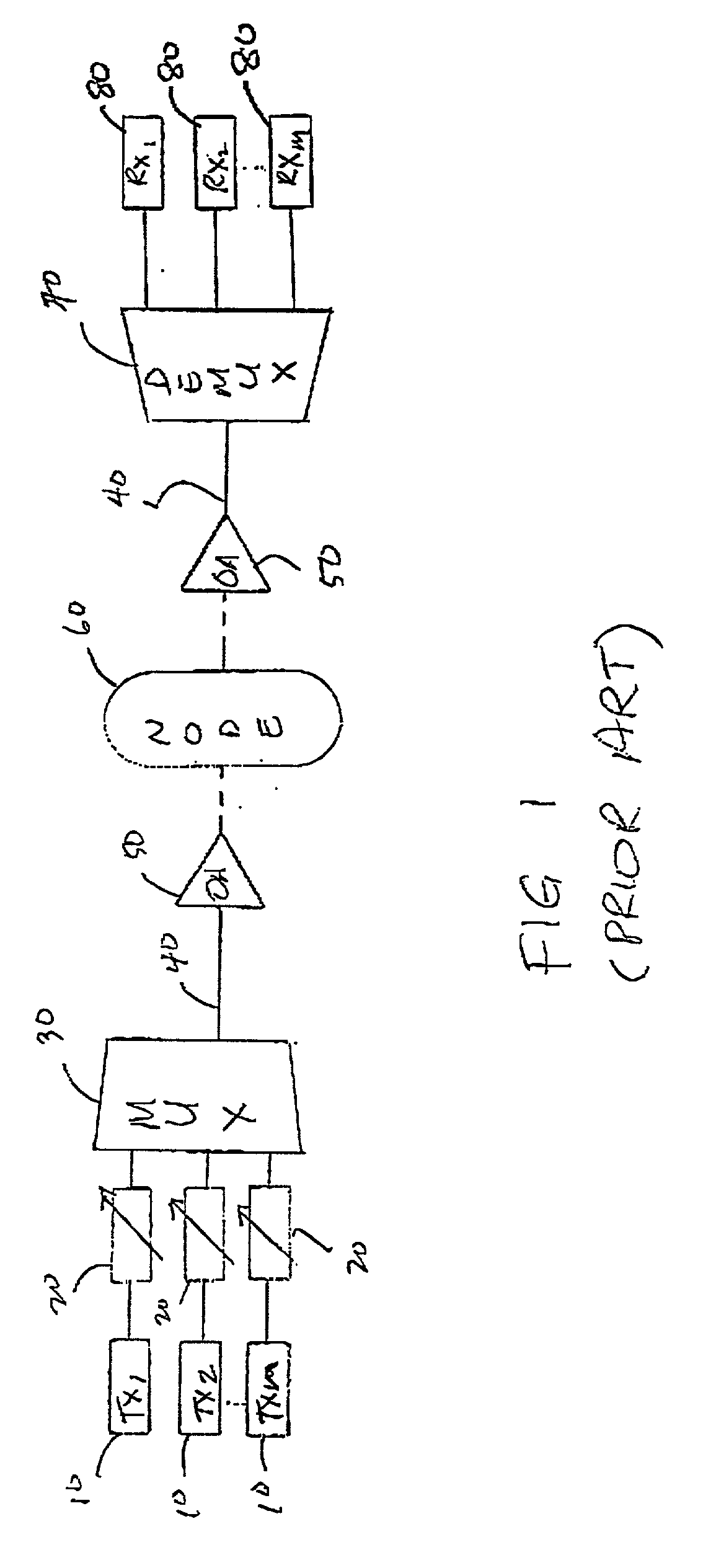
[0042] Referring to FIG. 1, a multi-channel transport system according to the prior art is illustrated. Transmitters 10 feed variable attenuators 20 which in turn feed a multiplexer 30. The multiplexer 30 multiplexes the channel from transmitters into an optical path such as an optical fiber line 40, which feeds into one or more optical amplifiers 50. These optical amplifiers 50 are gain flattened to provide equal gain to all the channels on the single line 40. Between the optical amplifiers 50 may be multiple nodes 60, only one being illustrated in FIG. 1. These nodes may add, drop, or switch channels from the single optical line 40. The gain equalized channels are then fed into a demultiplexer 70 where the channels are demultiplexed to be further sent to multiple receivers 80.

[0043] It should be noted that while FIG. 1 places the adjustable attenuators 20 between the transmitters 10 and the multiplexer 30, these attenuators may also be placed between the demultiplexer 70 and the r...


PUM


Abstract

A method and devices for individually controlling the signal strength of single or multiple optical channels. A controller module monitors the signal strength of channels and amplifies those that need amplifying while attenuating those that are too strong using the same Erbium doped fiber amplifier. A controllable compensation module receives at least one channel and, when required, can either amplify or attenuate the signal strength of the channels. The module can be constructed out of a single fiber with an associated pump laser. If the laser provides insufficient pumping power, the fiber acts as an attenuator. If the laser provides a higher level of pump power, the fiber acts as an amplifier.

Description

[0001] This application is a continuation-in-part application of U.S. application Ser. No. 09 / 781,254, filed Feb. 13, 2001.[0002] The present invention relates to optical network wavelength management and configuration and, more specifically, to a programmable optical processor.BACKGROUND TO THE INVENTION[0003] The unprecedented growth of the Internet, E-commerce, private networks, high resolution digital video, and voice over IP is dramatically changing the demand for high speed broadband networks. Dense Wavelength Division Multiplexing (DWDM) technology has been deployed and widely adopted, not only for long-haul backbone networks, but also for the metropolitan network market. The fundamental idea of DWDM technology is to simultaneously transmit multiple wavelengths over the same fiber. Systems based on DWDM often have optical amplifiers, especially Erbium doped fiber based amplifiers, to compensate for transmission losses incurred during transmission. However, theses optical ampl...

Claims


Application Information

Patent Timeline
IPC IPC(8): H04B10/08H04J14/02
CPCH04B10/077H04J14/0221H04B2210/258H04B10/07955H04J14/02214H04J14/02216
Inventor YANG, DAN DAN
Owner DOWSLAKE MICROSYST
Learn More