Methods of achieving optimal communications performance

a communication performance and optimal technology, applied in the field of optimal communication performance, can solve problems such as limiting the overall system capacity, and achieve the effects of increasing the measurement resolution of impulse responses, extending the bandwidth of the measurement capacity, and expanding the bandwidth of the measurement system

Inactive Publication Date: 2007-02-20
MASSACHUSETTS INST OF TECH
View PDF18 Cites 19 Cited by
  • Summary
  • Abstract
  • Description
  • Claims
  • Application Information

AI Technical Summary

Benefits of technology

[0045]The deconvolution approach expands the bandwidth of the measurement system by about a factor of two when using a wide bandwidth direct detection system, such as a photodetector and oscilloscope, which yields measurement bandwidths of ˜40 +GHz. The processor may also perform cross-correlation techniques to increase measur

Problems solved by technology

This, in turn, can reduce the effect of deleterious non-line

Method used


Image

  • Methods of achieving optimal communications performance
  • Methods of achieving optimal communications performance
  • Methods of achieving optimal communications performance

Examples


Embodiment Construction

[0066]A description of preferred embodiments of the invention follows.

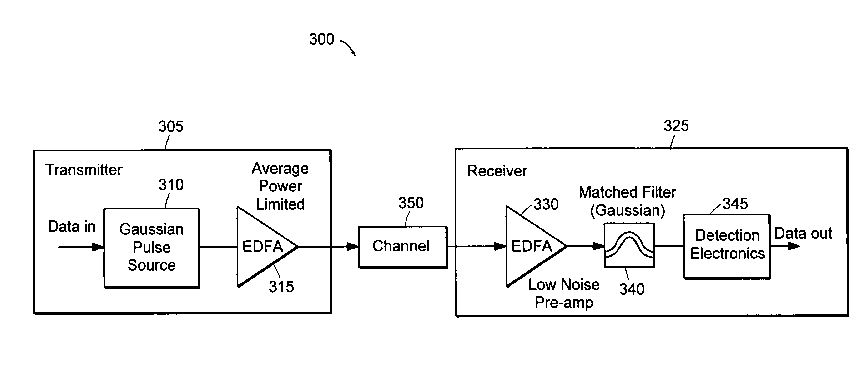
[0067]FIG. 3A is a schematic diagram of an experimental setup 300 used to demonstrate a matched optical link. The setup 300 includes a transmitter 305, receiver 325, and variable attenuator 320 optically disposed between the transmitter 305 and receiver 325. The variable attenuator 320 may be used to emulate channel effects such as loss, dispersion, and non-linearities in a communication channel.

[0068]The transmitter 305 includes a distributed feedback (DFB) master laser 420 followed by two external Mach-Zehnder modulators (MZM) 430, 435 in series. In this particular embodiment, one of the two MZMs 430 is driven sinusoidally to carve out approximately Gaussian pulses, and the other of the two MZMs 435 imparts a 5 Gbps data on the pulse stream. The master laser 420 and MzMs 430, 435 are hereafter referred to as a Gaussian pulse source 310.

[0069]Following the Gaussian pulse source 310, the transmitter 305 includes a...


PUM


Abstract

A system includes an optical transmitter that outputs an optical signal having a substantially Gaussian waveform and an optical receiver that is optically coupled to the optical transmitter and has an impulse response essentially matching the waveform. The impulse response and waveform preferably match in the time domain. The transmitter and receiver may be average-power-limited, using, for example, an erbium-doped fiber amplifier. To achieve a high signal-to-noise ratio, the waveform may be designed to minimize jitter, sample duration, matching parasitics, and inter-symbol interference (ISI). Such a waveform may be a return-to-zero (RZ) Gaussian or Gaussian-like waveform and may be transmitted in a variety of modulation formats. Further, the system may be used in WDM or TDM systems. A method for characterizing the time domain impulse response of an optical element used in the optical receiver is provided, where the method is optionally optimized using deconvolution and/or cross-correlation techniques.

Description

RELATED APPLICATION(S)[0001]This application claims the benefit of U.S. Provisional Application No. 60 / 276,003, filed on Mar. 15, 2001; the entire teachings of the above application are incorporated herein by reference.GOVERNMENT SUPPORT[0002]The invention was supported, in whole or in part, by a grant F19628-00-C-002 from United States Air Force. The Government has certain rights in the invention.BACKGROUND OF THE INVENTION[0003]High sensitivity optical communication links are vital for the design of future high-performance communication networks. FIG. 1 provides an example of such a network. This network includes satellite nodes 105 having free-space optical transmission channels 110. The network 100 also includes ground-based network nodes 115, such as central offices. Between the ground-based network nodes 115 are fiber optic or free space transmission channels 120. Both the satellite nodes 105 and ground-based nodes 115 include transmitters and receivers (not shown).[0004]It is...

Claims


Application Information

Patent Timeline
IPC IPC(8): G02B6/12H04B10/155
CPCH04B10/25137H04B10/508H04B10/5051H04B10/505
Inventor CAPLAN, DAVID O.ATIA, WALID A.
Owner MASSACHUSETTS INST OF TECH
Why Eureka
Try Eureka