
Glass ceramic composite of mirror blank

Inactive Publication Date: 2002-12-19
SCHOTT AG
View PDF0 Cites 12 Cited by
  • Summary
  • Abstract
  • Description
  • Claims
  • Application Information

AI Technical Summary

Benefits of technology

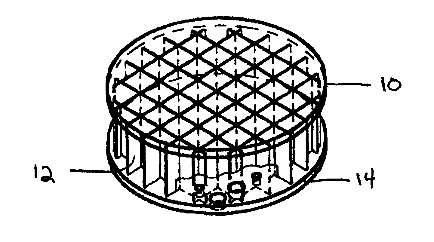
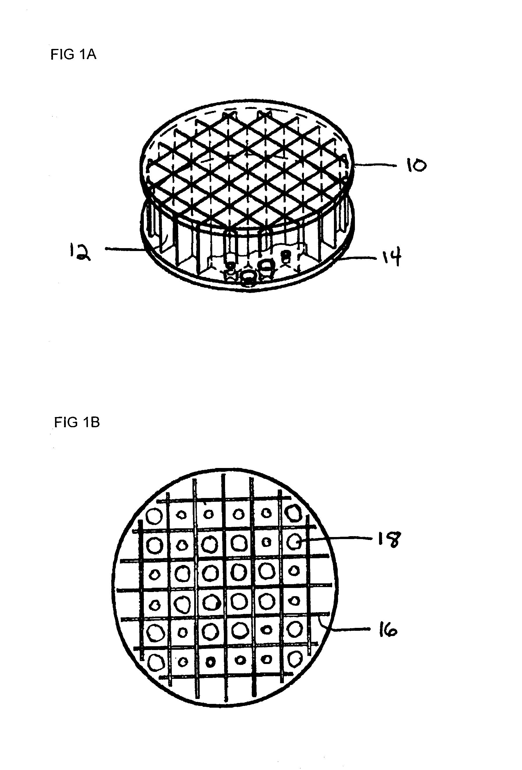
[0024] The present invention relates to a low-temperature process for the fabrication of lightweight composite glass ceramic structures, comprised, e.g., of a plurality (e.g., two or more) of glass ceramic components, said glass ceramic components each being polished sufficiently to form at least one joining surface on each component, providing a silicate-containing joining liquid to at least one of the joining surfaces, bringing the joining surfaces of the plurality of glass components together to form a joint, and allowing the joint to cure for a period of time at ambient temperature, whereby a cured joint is formed between said plurality of glass components. It also relates to a glass ceramic composite, comprising a plurality of glass ceramic components, said components being rigidly connected by a silicate-containing layer formed by curing a silicate-containing liquid between the glass ceramic components. The composites are preferably dehydrated by a carefully controlled dehydration process.

Problems solved by technology

However, these large segments of monolithic glass ceramic are often very massive.
Developing loading / unloading fixtures for operation at T>600.degree. C. is complex and expensive.
The viscosity of glass is sufficiently low at these temperatures, such that limited flow (deformation) can occur.
This deformation can cause gross dimensional changes, which can yield a defective mirror blank.
Such furnaces must be custom-made and are often very expensive.
This shrinkage can cause joint stresses that result in deformation and / or catastrophic failure of the mirror blank during joining.
Yet another difficulty encountered in the prior art is that light-weighted mirror blanks can fail during high temperature joining when thermally induced stresses form at the joint interfaces (especially during cooling to room temperature).
Such joint failure results in a 100% loss after a tremendous amount of value has been added to the mirror blank (i.e., machining, polishing, water-jet cutting, assembly, high temperature fixturing, etc.).

Method used


Image

  • Glass ceramic composite of mirror blank
  • Glass ceramic composite of mirror blank
  • Glass ceramic composite of mirror blank

Examples


Embodiment Construction

[0112] Zerodur.RTM. samples with approximate dimensions of 60.times.25.times.25 mm were used for all joining experiments. One of the 25.times.25 mm faces on each sample was polished, with a surface figure of at least 1 / 3.lambda.(200 nm peak to valley, this surface will be referred to as the joining surface), while the other 25.times.25mm face was simply polished to a transparent finish.

[0113] The joining surfaces were cleaned using various solutions. First, the samples were ultrasonically cleaned in a 10:90 volumetric ratio of Micro Cleaning Solution and deionized H.sub.2O. The samples were then rinsed with deionized H.sub.2O before being ultrasonically cleaned with 3.0 M KOH.sub.(aq) solution. After cleaning with KOH.sub.(aq) solution, the samples were rinsed with deionized H.sub.2O, ethanol and methanol before being dried with deionized N.sub.2 gas. Finally, a CO.sub.2 sno-gun was used to remove particulate debris from the joining surfaces. The clean samples were placed within a c...


PUM

PropertyMeasurementUnit
Timeaaaaaaaaaa
Timeaaaaaaaaaa
Timeaaaaaaaaaa

Abstract

A method for fabricating composite light-weighted glass ceramics, suitable for use as, e.g. mirror blanks or microlithography stages, at low temperatures is disclosed. Component pieces are polished then joined at low temperature using a silicate-containing joining liquid. Assembly is then performed in such a way that the joining liquid forms an interface between each component. After a period of low or slightly elevated temperature curing, rigid joints are formed throughout and the composite is dimensionally, vibrationally, and temperature stable and can withstand tensile stresses >4000 psi. The room-temperature cured composite can be heat treated using a slow, systematic temperature increase to dehydrate the joints. A sealing coating may optionally be provided to prevent excess dried joining liquid from flaking off the formed joint.

Description

[0001] I. Field of the Invention[0002] The invention relates to the field of glass ceramic composite structures and methods for forming composite glass ceramic structures using a low temperature joining process.[0003] II. Description of the Prior Art[0004] Glass ceramics, which generally consist of an inorganic, non-porous material having a crystalline phase and a glassy phase, are known for specialized applications. Such glass ceramics are manufactured by selecting suitable raw materials, melting, refining, homogenizing, and then hot forming the material into a glassy blank. After the glassy blank is cooled and annealed, a temperature treatment follows whereby the glassy blank is transformed into a glass ceramic by controlled volume crystallization (ceramization). Ceramization is a two-step process; nuclei are formed within the glass at one temperature, and then grown at a higher temperature. The dual structure of the glass ceramic material can impart very special properties, inclu...

Claims


Application Information

Patent Timeline
IPC IPC(8): C03C27/10C03C27/04C03C27/06
CPCC03C27/044C03C27/06Y10T428/24273Y10T428/24322Y10T428/21
Inventor CONZONE, SAMUEL DAVIDMARKER, ALEXANDER J. III
Owner SCHOTT AG
Learn More