Single cell for fuel cell and solid oxide fuel cell

a fuel cell and single cell technology, applied in the direction of cell components, final product manufacturing, sustainable manufacturing/processing, etc., can solve the problems of loss of generation power output, achieve the effect of enhancing generation power output, compact electrolyte film, and reducing conductivity of electrolyte layer

Inactive Publication Date: 2003-01-16
NISSAN MOTOR CO LTD
View PDF2 Cites 47 Cited by
  • Summary
  • Abstract
  • Description
  • Claims
  • Application Information

AI Technical Summary

Benefits of technology

0014] As described above, in the solid oxide fuel cell, it is important to reduce the conductivity of the electrolyte layer by thinning the solid electrolyte layer in order to enhance the generation power output. Meanwhile, since the fuel gas and the air have the electrolyte layer as a partition, compactness of the electrolyte film also becomes important. If there is a pinhole in the electrolyte film and a leak occurs even a little from the pinhole, the fuel gas and the air react directly, leading to the loss of the generation power output.

Problems solved by technology

If there is a pinhole in the electrolyte film and a leak occurs even a little from the pinhole, the fuel gas and the air react directly, leading to the loss of the generation power output.

Method used


Image

  • Single cell for fuel cell and solid oxide fuel cell
  • Single cell for fuel cell and solid oxide fuel cell
  • Single cell for fuel cell and solid oxide fuel cell

Examples


example 1

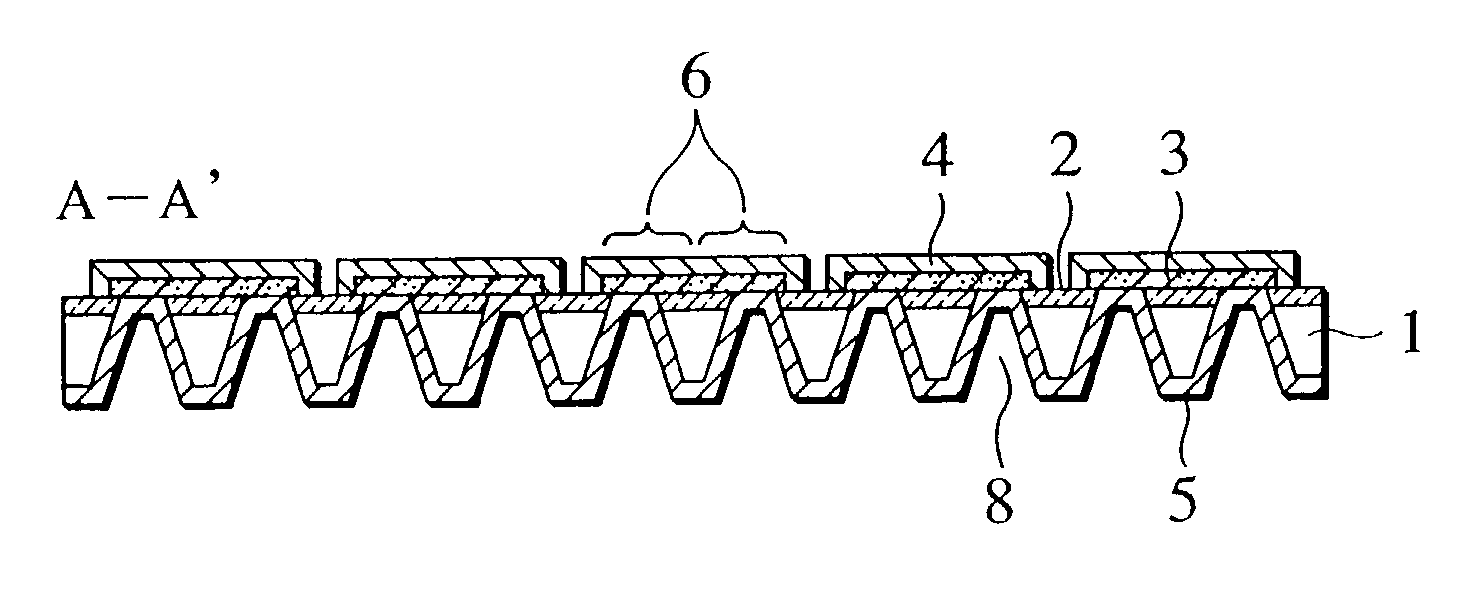
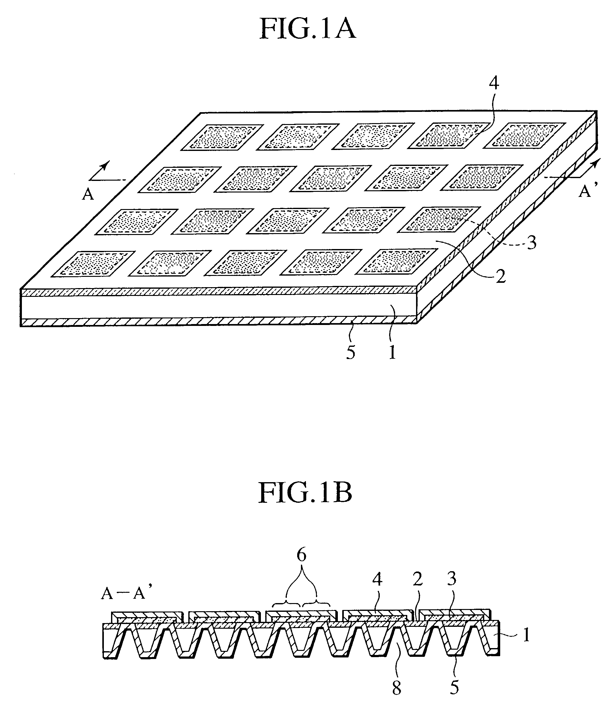
[0194] FIG. 1A is a perspective view of a cell plate of example 1, and FIG. 1B is a sectional view of this cell plate along a section line A-A' of FIG. 1A. 10 times 10 pieces of cells 6 are formed on a Si substrate 1 of 10 cm square. Each cell 6 has a rectangular opening 8 of about 2 mm square.

[0195] On one surface of the Si substrate 1 (hereinafter, referred to as a "upper surface"), on which a plurality of the openings 8 are formed, an insulating and stress absorbing layer 2 is formed. Moreover, on the upper surface of the substrate, on which the insulating and stress absorbing layer 2 is formed, electrolyte layers 3 and upper electrode layers 4 are formed so as to cover the openings 8. The other surface of the substrate (hereinafter, referred to as a "lower surface") is coated with a lower electrode layer 5, and on the openings 8, the lower electrode layer 5 is exposed to the upper surface of the Si substrate 1 and directly contacts the electrolyte layers 3.

[0196] Hereinafter, de...

example 2

[0207] By use of a method similar to that in the above-described example 1, fabricated was a cell plate, on which the insulating and stress absorbing layer 2 was made of various materials. Moreover, in addition to this, also with regard to the electrolyte layer 3, cell plates of various patterns shown in FIG. 1A and FIGS. 5A to 5C were fabricated. These cell plates were placed in the electric furnace, and a heat treatment test at a temperature of 700.degree. C. (temperature rising rate: 300.degree. C. / Hr) in the atmosphere was executed. Results obtained are shown in a table of FIG. 6.

[0208] The pattern of FIG. 5A shows that the electrolyte layer pattern is separated for every four openings and corners of each separated pattern is chamfered. The pattern of FIG. 5B shows that an independent circular pattern is formed for every opening. The pattern of FIG. 5C shows that a continuous electrolyte layer pattern is formed on the entire surface of the cell plate.

[0209] Note that, .largecirc...

example 3

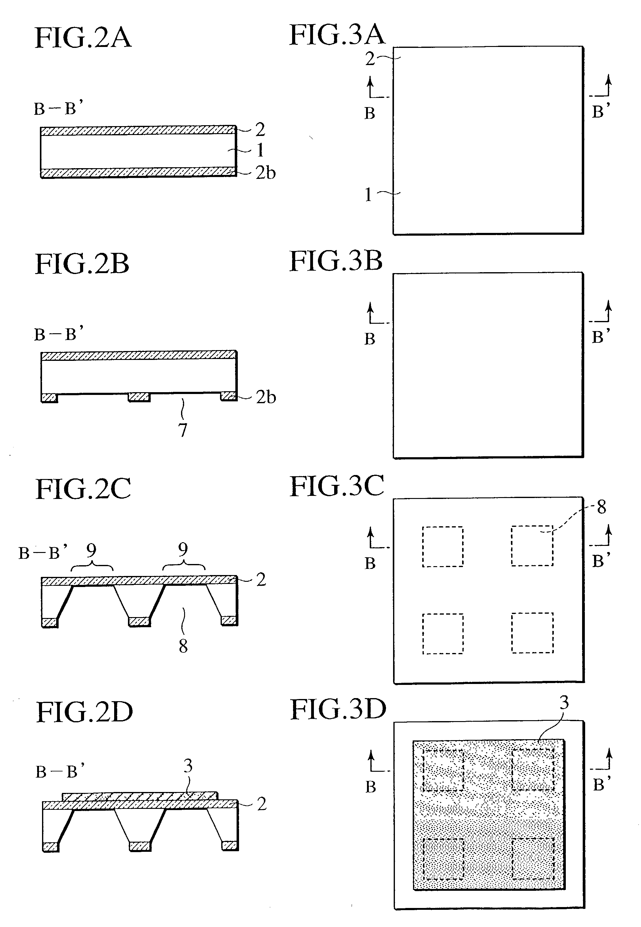
[0212] Example 3 used a Si substrate of 10 cm square similar to that of example 1, and a cell plate manufactured in accordance with manufacturing steps shown in FIGS. 7A to 7H and FIGS. 8A to 8H. FIGS. 7A to 7H are partial sectional views of the cell plate in The respective manufacturing steps, and FIGS. 8A to 8H are partial plan views of the cell plate in the respective manufacturing steps.

[0213] First, silicon nitride films as the insulating and stress absorbing layers 2 (2a) are deposited in thickness of 200 nm on the both surfaces of the Si substrate 1 by the low pressure CVD method, and a PSG layer as a reinforcement layer 12 is deposited in thickness of 100 nm on the upper surface of the substrate by a normal pressure CVD method (FIG. 7A and FIG. 8A).

[0214] Similarly to example 1, a desired region of this silicon nitride film 2a on the lower surface of the substrate is removed by the photolithography and by the chemical dry etching using CF.sub.4 gas, thus forming silicon expo...


PUM

PropertyMeasurementUnit
thicknessaaaaaaaaaa
temperatureaaaaaaaaaa
thicknessaaaaaaaaaa

Abstract

A single cell for a solid oxide fuel cell, in which a solid electrolyte layer is sandwiched by an upper electrode layer and a lower electrode layer. This single cell includes a substrate having openings and an insulating and stress absorbing layer stacked on an upper surface of this substrate. The solid electrolyte layer is formed on an upper surface of the insulating and stress absorbing layer so as to cover the openings, the upper electrode layer is stacked on an upper surface of the solid electrolyte layer, and the lower electrode layer is coated on a lower surface of the solid electrolyte layer via the openings from a lower surface of the substrate. A cell plate, in which these single cells are disposed two-dimensionally on a common substrate. Furthermore, a solid oxide fuel cell, in which these cell plates and plate-shaped separators including gas passages on both surfaces thereof are alternately stacked.

Description

[0001] The present invention relates to a solid oxide fuel cell (SOFC) using solid electrolyte and obtaining electric energy by an electrochemical reaction, more specifically, to a single cell having electrodes and the solid electrolyte between the electrodes and a method of manufacturing the same, and to a solid oxide fuel cell including this single cell.[0002] Recent years, as a clean energy source capable of highly efficient energy conversion and friendly to the global environment, a fuel cell has attracted an attention. Among a variety of the fuel cells, a solid oxide fuel cell is the one, in which oxide ion conductive solid electrolyte such as yttria stabilized zirconia is used as electrolyte, and porous electrodes are attached onto both surfaces (back and front surfaces) thereof. The solid oxide fuel cell is a cell in a form, in which the solid electrolyte is used as a partition, fuel gas such as hydrogen and hydrocarbon is supplied to a surface of the partition on one electro...

Claims


Application Information

Patent Timeline
Patent Type & Authority Applications(United States)
IPC IPC(8): H01M4/88H01M8/02H01M4/86H01M8/12H01M8/24
CPCH01M8/1206H01M8/1213H01M8/1226H01M8/1286H01M8/2425H01M2300/0074Y02E60/521Y02E60/525H01M8/1231Y02P70/50Y02E60/50H01M8/2428H01M8/2432H01M8/12H01M8/02H01M8/24H01M8/2404
Inventor KUSHIBIKI, KEIKOSATO, FUMINORIHARA, NAOKIYAMANAKA, MITSUGUHATANO, MASAHARUUCHIYAMA, MAKOTOSHIBATA, ITARUFUKUZAWA, TATSUHIRO
Owner NISSAN MOTOR CO LTD
Why Eureka
Try Eureka