Substance delivery apparatus and a method of delivering a therapeutic substance to an anatomical passageway

a technology of anatomical passageway and substance, applied in the field of medical devices, can solve the problems of limited quantity of substance that can be impregnated in the polymeric carrier, death of medial smooth muscle cells, adverse or toxic side effects for patients,

Inactive Publication Date: 2003-02-27
ABBOTT CARDIOVASCULAR
View PDF65 Cites 347 Cited by
  • Summary
  • Abstract
  • Description
  • Claims
  • Application Information

AI Technical Summary

Problems solved by technology

Angioplasty or other vascular procedures injure the vessel walls, removing the vascular endothelium, disturbing the tunica intima, and causing the death of medial smooth muscle cells.
In order to provide an efficacious concentration to the target site, systemic administration of such medication often produces adverse or toxic side effects for the patient.
A disadvantage associated with the use of medicated stents is that the quantity of the substance that can be impregnated in the polymeric carrier is limited.
An increase in the profile of the coating significantly limits the applications for which the stents can be used.
Another disadvantage associated with the use of medicated stents is that the polymeric carrier is only capable of applying the therapeutic substance to the inner surface of the tunica intima layer of the vessel.
The polymeric carrier is incapable of significantly introducing a therapeutic substance to the tunica adventitia or the tunica media layers of the vessel.
A shortcoming associated with this procedure is that the therapeutic substance is contiguously carried off in the patient's blood steam as it is being discharged from the balloon, which results in an ineffective treatment of the target site and adverse exposure of the substance to healthy tissues.

Method used


Image

  • Substance delivery apparatus and a method of delivering a therapeutic substance to an anatomical passageway
  • Substance delivery apparatus and a method of delivering a therapeutic substance to an anatomical passageway
  • Substance delivery apparatus and a method of delivering a therapeutic substance to an anatomical passageway

Examples


Embodiment Construction

Apparatus

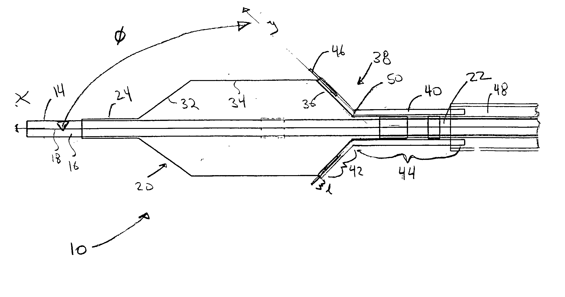
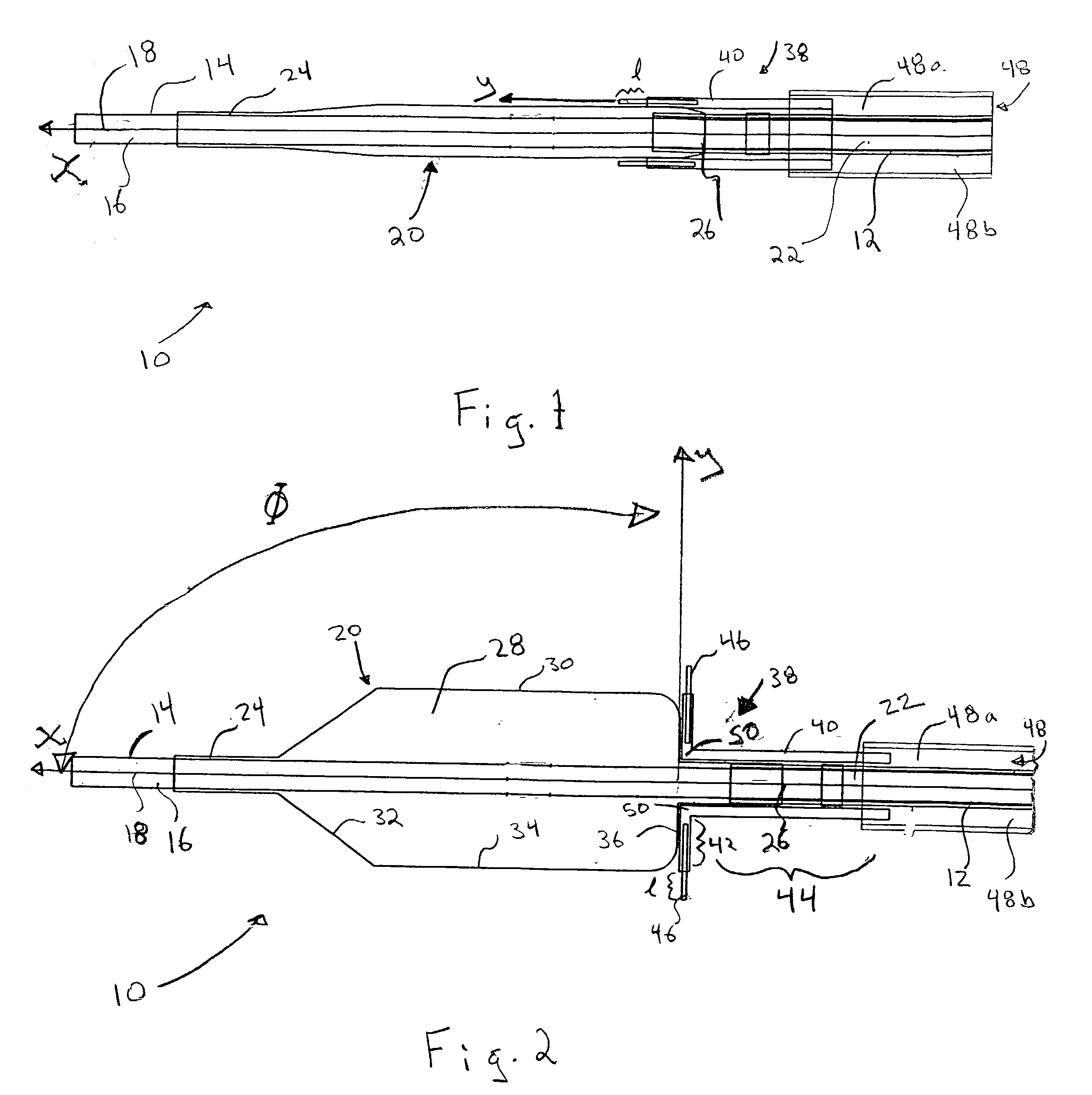
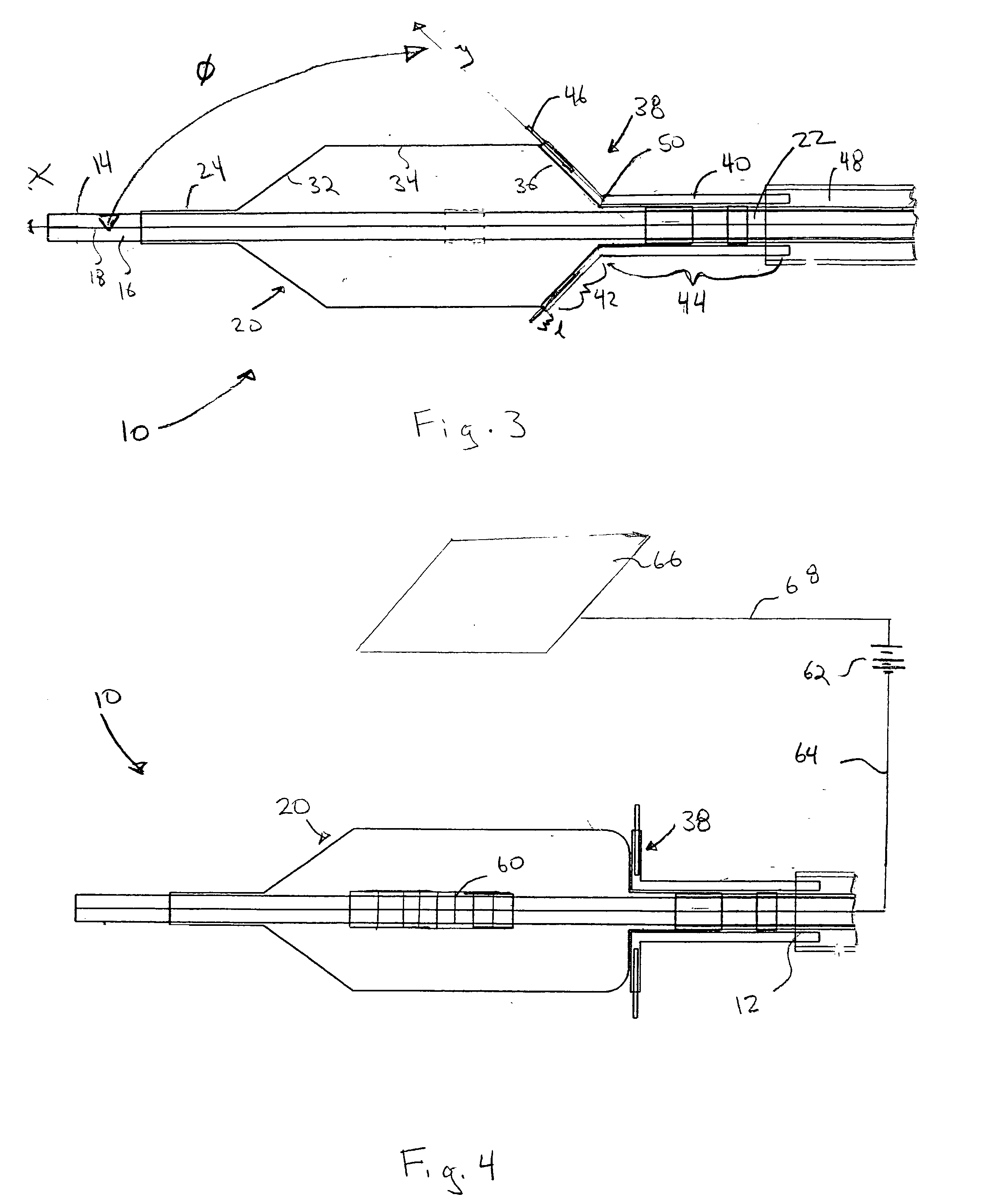
[0021] Referring now to the drawings, wherein similar parts are identified by like reference numerals, FIGS. 1 and 2 illustrate a substance delivery apparatus in accordance with one embodiment of the invention. In general, the substance delivery apparatus provides a system for delivering a substance, such as a therapeutic substance or a combination of therapeutic substances, to or through a desired area of a passageway in order to treat a localized area of the passageway or to treat a localized area of tissue located adjacent to the passageway. The substance delivery apparatus includes a catheter assembly 10, which is intended to broadly include any medical device design for insertion into a body passageway to permit injection and / or withdrawal of fluids, to maintain the patency of the passageway, or for any other purpose. It is contemplated that the substance delivery apparatus has applicability for use with any biological passageway, including blood vessels, urinary tract...


PUM


Abstract

A catheter assembly is provided having a balloon disposed at the distal end thereof. The balloon is capable of being inflated to selectively dilate from a collapsed configuration to an expanded configuration. The balloon is also capable of being deflated after inflation to return to the collapsed configuration or a deflated profile. A syringe assembly is in fluid communication with a delivery lumen of the catheter assembly for allowing a therapeutic substance to be injected into a tissue of a passageway. The syringe assembly includes a portion capable of pivoting from a first position towards a second position when the balloon is being inflated from the collapsed configuration to the expanded configuration. The portion of the syringe assembly is also capable of pivoting from the second position back towards the first position when the balloon is being deflated. The balloon can be made from a porous membrane to allow a therapeutic substance that is supplied into the balloon to be discharged out from the porous membrane.

Description

[0001] 1. Field of the Invention[0002] The present invention pertains generally to a medical device useful for delivering a substance to a biological passageway. More specifically, the present invention pertains to a catheter device having a syringe assembly useful for delivering a therapeutic substance to a passageway, such as a blood vessel.[0003] 1. Description of the Related Art[0004] Percutaneous transluminal coronary angioplasty (PTCA) is a procedure for treating heart disease. A catheter assembly having a balloon portion is introduced percutaneously into the cardiovascular system of a patient via the brachial or femoral artery. The catheter assembly is advanced through the coronary vasculature until the balloon portion is positioned across the occlusive lesion. Once in position across the lesion, the balloon is inflated to a predetermined size to radially compress the atherosclerotic plaque of the lesion against the inner wall of the artery to dilate the lumen. The balloon is...

Claims


Application Information

Patent Timeline
Patent Type & Authority Applications(United States)
IPC IPC(8): A61F2/958A61M5/32A61M5/34A61M25/00A61M29/02
CPCA61M25/0084A61M25/10A61M25/104A61M2005/341A61M2025/0004A61M2025/0086A61M2025/0087A61M2025/0096A61M2025/105
Inventor RAY, PINAKIBHAT, VINAYAK D.MIRZAEE, DARYUSH
Owner ABBOTT CARDIOVASCULAR
Why Eureka
Try Eureka