Accelarated water evaporation system

a technology of evaporation system and evaporation chamber, which is applied in the direction of machine/engine, lighting and heating apparatus, separation processes, etc., can solve the problems of liquids that cannot be re-evaporated, liquids generated from well drilling operations are typically left for long periods of time to slowly evaporate, and liquids cannot be re-evaporated, etc., to achieve cost-effective and eliminate long-term problems of water production

Inactive Publication Date: 2003-04-03
RESOURCE WEST
View PDF0 Cites 9 Cited by
  • Summary
  • Abstract
  • Description
  • Claims
  • Application Information

AI Technical Summary

Benefits of technology

0028] Another significant object of an embodiment of the invention can be to use natural gas produced at a well head at a low enough volume or pressure during the liquid-gas conversion process such that it has essentially no effect on the ongoing production rates of the well.
0029] Yet another object of an embodiment of the invention can be to provide a method of accelerated water evaporation which may be environmentally acceptable from both a regulatory and a consumers perspective.
0030] Still another object of an embodiment of the invention can be to dispose of water in a manner which substantially eliminates the long term problems of water production during the production life of an oil or gas well.
0031] Another object of an embodiment of the invention can be to provide an accelerated water evaporation system that can be cost effective both with respect to operation but also with respect to maintenance.

Problems solved by technology

Liquids can pose significant problems with respect to transportation, storage, disposal; volume reduction, distillation, or purification; or contaminant deposition, precipitation, or accumulation, and the like.
As such, liquids generated from well drilling operations are typically left for long periods of time to slowly evaporate.
Under recently promulgated regulations, however, liquids may not remain in reserve pits to evaporate for such long periods of time, and removal of liquids from remote locations may be impossible or simply impracticable.
While other examples of liquid handling, storage, or disposal problems may be provided within the context of the oil or gas industry, other industries, including both small and large businesses, also have liquid management problems relating to conversion of liquids to gases, the reduction of liquid volume, removal of contaminants from liquids, purification of liquids, distillation of liquids, disposal of liquids, or processing of liquids for direct release into the environment, the watershed, or into sewage systems.
Even though there is an increased number and variety of liquid-gas converters and methods for converting liquids to gas available to the consumer a number of significant problems remain unresolved with respect to converting liquids to gas, reducing the volume of liquids, the removal, deposition, or accumulation of contaminants from liquids, or the processing of liquids for direct release into the environment, watershed or sewage system.
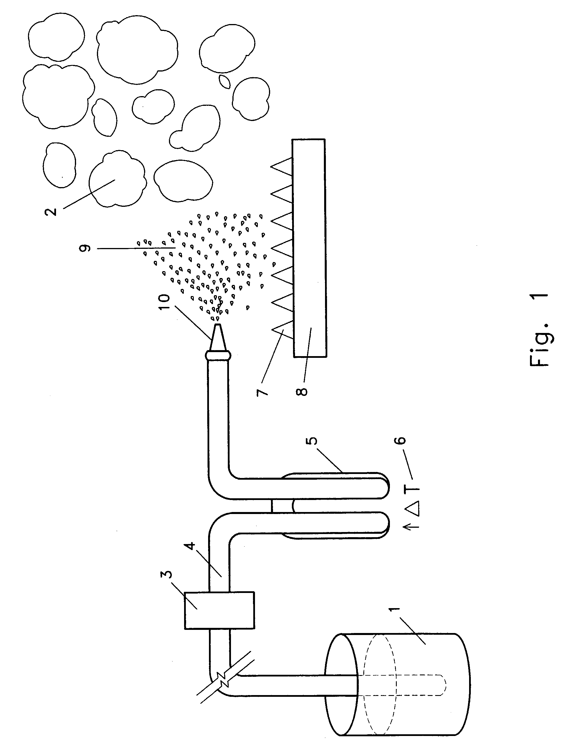
A significant problem with existing liquid management technology may be that natural liquid evaporation rates are slow.
However, liquid spraying methods may still be too slow for operators to meet statutory reclamation deadlines, may be effected by or not work at lower temperatures, or may not meet environmental statutory or regulatory requirements.
A practical problem with spraying liquids into the atmosphere to accelerate evaporation may be that wind will carry the sprayed water away from the containment area and contaminate the surrounding soil or may percolate to the underlying ground water.
Another significant problem with existing liquid management technology may be that it is incompatible or impractical to use with large volumes of liquid.
Another significant problem with existing liquid management technology may be that liquid is heated in an open container to convert the liquid to a gas.
One aspect of this problem, may be that the liquid cannot be heated substantially above the boiling point of the liquid to facilitate the conversion of the liquid to a gas.
Another aspect of this problem may be that liquids can be very alkaline or very acidic, depending on the concentration of substances dissolved in the liquids, and such liquids may damage the container or other components submersed in the liquid.
Another significant problem with existing liquid management technology may be that substances dissolved in a liquid are difficult to isolate, accumulate, or remove from deposition surfaces.
Another significant problem with existing liquid management technology may be that the devices cannot be run continuously.
One aspect of this problem can be that the device cannot process or has a reduced processing capability during the period in which it is being recharged with additional liquid.
A second aspect of this problem may be that the device cannot process additional liquid because solids, precipitates, or concentrates must be removed, or the device otherwise cleaned prior to the processing of additional liquid.
Another significant problem with existing liquid management technology may be that exhaust fans or blowers are required to move gases generated by conventional liquid-gas converters, or to move exhaust from the combustion of fuels.
As such, to the extent that these conventional types of liquid to gas convertors have blowers, fans, or the like to move generated gas, steam, vapor, or the like, they may be more complex, require greater maintenance, be more costly to build, or be more prone to failure than less complex liquid-gas convertors.
Another significant problem with existing liquid management technology may be that liquids are transported to storage or disposal sites.
One aspect of this problem is the high cost of transporting the liquids from the site of generation to the storage or disposal facility.
Since liquids may be continuously generated, the expense of transporting, storage, or disposal can be an ongoing expense for the life of a business, or for the life of an oil or gas well.
A second aspect of this problem can be cradle-to-grave laws that may make the generator of the liquid liable for any injury or damage caused by the liquid during transportation, or even liable during the entire period of storage, disposal, or upon return to the environment or watershed.

Method used


Image

  • Accelarated water evaporation system
  • Accelarated water evaporation system
  • Accelarated water evaporation system

Examples


Embodiment Construction

[0039] The invention relates to apparatuses and methods for the conversion of liquids to gases. Several basic embodiments of the invention are first described followed by preferred embodiments of the invention including the best mode of use.

[0040] First referring to FIG. 1, an embodiment of the invention to convert a liquid (1) to a gas (2) is illustrated. With respect to embodiments of the invention of this type, a pressurization element (3) is responsive to liquid (1). In certain embodiments of the invention, the pressurization element (3) can comprise a positive displacement type pump. Alternately, in other embodiments of the invention the pressurization element (3) can comprise compressed air means. With respect to the operation of the compressed air means, compressed air can be forced into the liquid (1) within a liquid compression zone (4). The liquid compression zone can for example be a length of tube, a closed container, or the like. As the compressed air displaces the liqu...


PUM


Abstract

A gas to liquid converter to convert liquids (1) to gas (2) that can include a liquid pressurization element (3), a liquid preheating element (5), and a nozzle (10) to disperse liquids into energy (7) generated by an energy source (8). The gas to liquid converter can be located inside an enclosure (17) and substances dissolved in the liquid can accumulate as solids (13) on deposition surface (12) of the enclosure as the liquid (1) converts to gas (2). Condesation of a portion of the gas (2) generated can be combined with the solids (13) for continuous removal of such solids (13) from the enclosure (17). A gas expansion compensator can generate a pressure gradient (24) to move the volume of gas generated from the liquid from the enclosure (17).

Description

I. TECHNICAL FIELD[0001] A system for the conversion of liquids to gases that may be used in the context of various technologies to reduce the volume of liquids, remove and accumulate dissolved solids from liquids, produce distillates, purify water, introduce liquids into the surrounding environment or the watershed, generate expansion gases as a source of energy, or the like. Specifically, certain embodiments of the invention can be used to accelerate the evaporation of liquids that are produced from oil and gas well drilling and completion processes.II. BACKGROUND[0002] Liquids can pose significant problems with respect to transportation, storage, disposal; volume reduction, distillation, or purification; or contaminant deposition, precipitation, or accumulation, and the like. Certain of these problems have been made more acute by recent changes in federal and state laws that have generated more stringent environmental regulations with respect to storage or disposal of liquids by ...

Claims


Application Information

Patent Timeline
Patent Type & Authority Applications(United States)
IPC IPC(8): B01D1/00B01D1/16F22B3/04F22B27/16
CPCB01D1/0011F22B27/16F22B3/04B01D1/16
Inventor HAYS, HERBIE JACKHAYS, WILLIAM MERLEQUEZADA, ARTURO
Owner RESOURCE WEST
Why Eureka
Try Eureka