Method and system for determining transmission path delay

Inactive Publication Date: 2003-06-05
NOKIA SOLUTIONS & NETWORKS OY
View PDF0 Cites 12 Cited by
  • Summary
  • Abstract
  • Description
  • Claims
  • Application Information

AI Technical Summary

Benefits of technology

0007] The present invention seeks to provide an improved method and apparatus. According to at least one embodiment of the present invention, a method is provided in which a transmission path delay is determined based on a measured time

Problems solved by technology

A problem arises from the transmission media used between the different driver / receiver pairs because the delay caused by the media may vary according to each pair.
This, however, complicates the planning of the device and, in addition, may require an additional buffer memory.
This solution is not, however, feasible for base stations, where the length of the transmission media between the transceiver and the masthead amplifier may vary from dozens of centimeters to dozens of meters, for example.
The solution requires double wiring and, since it is a continuous operation, it increases the power consumption of the device.

Method used


Image

  • Method and system for determining transmission path delay
  • Method and system for determining transmission path delay
  • Method and system for determining transmission path delay

Examples


Embodiment Construction

[0016] Embodiments of the invention are based on the fact that the transmission media between the electronic circuits is normally subjected to impedance matching to prevent reflections. Now impedance matching configuration is used to create reflections in the transmission media for estimating the transmission delay caused by the transmission media. In other words, a non-ideal situation is deliberately created in an attempt to make use of it.

[0017] The solution is relatively simple to implement, it does not need to be applied during the entire transmission of the payload, and it does not require separate wiring for receiving feedback.

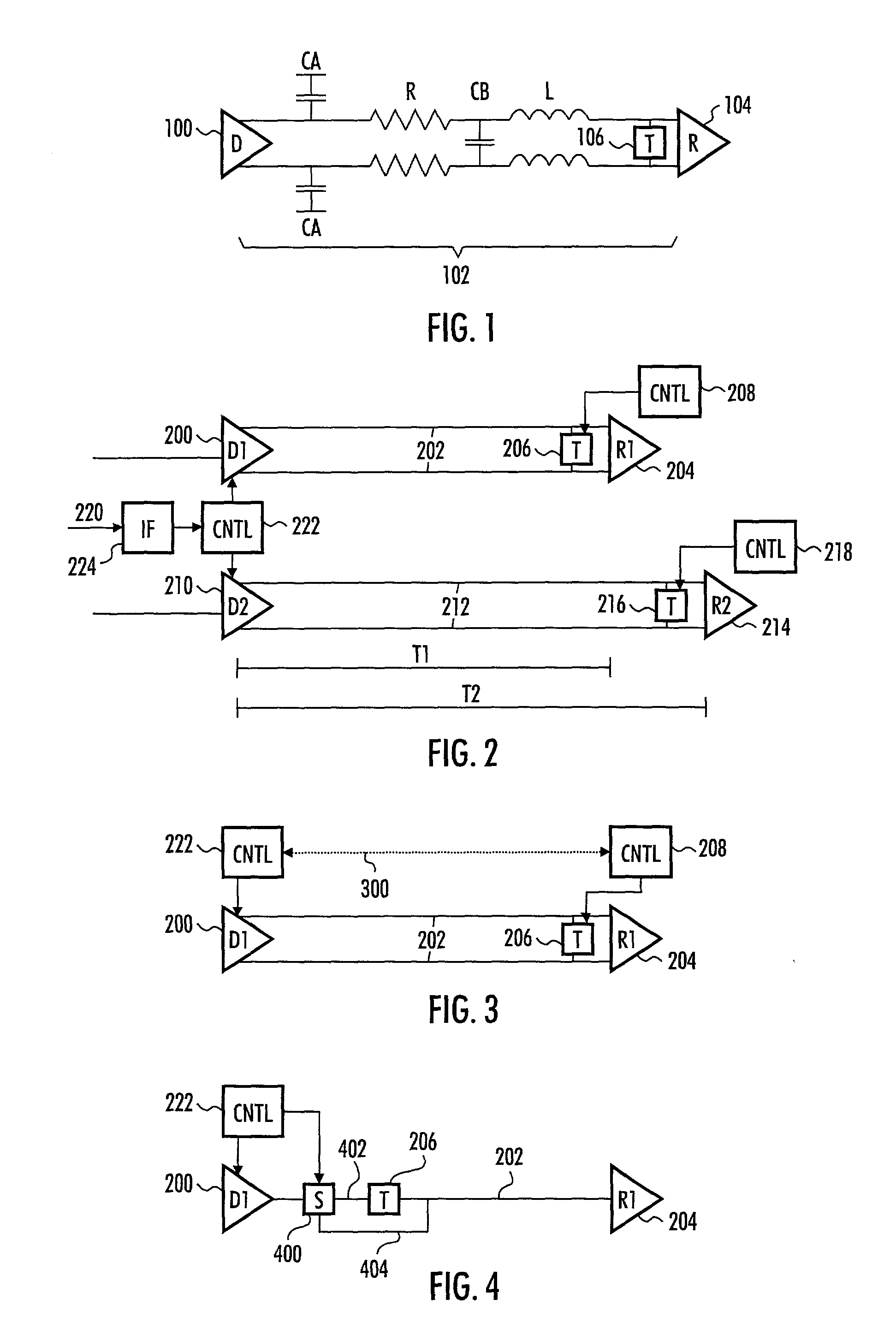
[0018] FIG. 1 shows one implementation of a driver / receiver pair, in which a driver 100 is coupled to a receiver 104 by a transmission path 102. The transmission path 102 may be implemented as a transmission line, for example. The transmission path 102 may comprise parasitic capacitance CA, CB, resistance R and inductance L.

[0019] In the transmission of ...


PUM


Abstract

The invention relates to transmission path delay determination between a first and a second electronic circuit coupled to each other by a transmission path. A determination method includes, among other operations, transmitting at least one test signal from a first electronic circuit to a second electronic circuit, receiving at the first electronic circuit a reflection of the test signal from the second electronic circuit, measuring a time duration necessary for receiving the reflection of the test signal, determining a transmission path delay as half of the measured time duration, reconfiguring the line impedance termination between the first and second electronic circuit, adjusting the timing of a payload signal on the basis of the transmission path delay, and transmitting the payload signal between the first and second electronic circuit.

Description

FIELD[0001] The invention relates to transmission path delay determination.[0002] In electronic devices, such as base stations of radio systems, signals are transmitted between different electronic circuits. The circuits may form what is known as a driver / receiver pair, in which the driver transmits a data signal, such as a clock signal, to the receiver.[0003] The transmission media may be, for example, a wire printed on a circuit board, a cable, connectors, or the like, placed between and coupling the driver and the receiver, and will always delay propagation of the signal. An electronic device may comprise a plural number of driver / receiver pairs, and the elements of the pairs may appear in diverse parts of the electronic device. For example, a base station may comprise a driver, which may be a transceiver, and a receiver, which may be a frequency amplifier, frequency synthesizer or masthead amplifier connected to the transceiver.[0004] An electronic device may comprise a pluralit...

Claims


Application Information

Patent Timeline
IPC IPC(8): H04B17/00
CPCH04B3/462H04B17/21H04B17/11
Inventor PARTANEN, TIMO
Owner NOKIA SOLUTIONS & NETWORKS OY
Why Eureka
Try Eureka