Cryogenically enhanced intravascular interventions

Inactive Publication Date: 2003-06-12
BOSTON SCI SCIMED INC
View PDF17 Cites 73 Cited by
  • Summary
  • Abstract
  • Description
  • Claims
  • Application Information

AI Technical Summary

Benefits of technology

[0013] Typically, the cooling will reduce stenosis by a relative amount of at least about 5% of the stenosis which would otherwise occur in the vessel, preferably by at least about 10%, and more preferably by at least about 25%. Ideally, the cooling step effects a relative reduction of the stenosis of at least about 50% of the equivalent vessel region stenosis, and may even be tailored to reduce stenosis by about 80% or more. Measured reductions in absolute stenosis percentages often measure more than 6%, preferably being more than 8%, and in experiments described herein, have been shown to be more than 15% and even better than 22%. Such benefits are provided by cooling times in a range from about 10 to about 30 seconds, and with the cooling temperature of the inner surface of the blood vessel being in a range from about 4.degree. C. to about -31.degree. C. (preferably being in a range from about -5.degree. C. to about -15.degree. C.).
[0014] In another aspect, the invention provides a method for inhibiting restenosis of a blood vessel region of a mammal. The blood vessel region is subjected to a primary treatment effecting an initial reduction in stenosis and inducing the restenosis. Typical primary treatments include directional angioplasty, arthrectomy, rotational arthrectomy, laser angioplasty, stenting, and the like. The method comprises cooling an inner surface of the blood vessel region to a temperature and for a time sufficient to remodel the blood vessel region such that observed restenosis of the blood vessel is measurably inhibited. Typically, the cooling step induces at least one of apoptosis, cell membrane damage, and programmed cell death so as to provide these advantages.

Problems solved by technology

More specifically, the cooling process may weaken the vessel and allows it to be expanded with a much lower balloon pressure than with conventional uncooled angioplasty.

Method used


Image

  • Cryogenically enhanced intravascular interventions
  • Cryogenically enhanced intravascular interventions
  • Cryogenically enhanced intravascular interventions

Examples


Embodiment Construction

[0028] The devices, systems, and methods of the present invention are related to those of co-pending U.S. patent application Ser. No. 09 / 203,011, filed on Dec. 1, 1998 for an Apparatus and Method for Cryogenic Inhibition of Hyperplasia. That application is assigned to the present assignee, and its full disclosure is incorporated herein by reference.

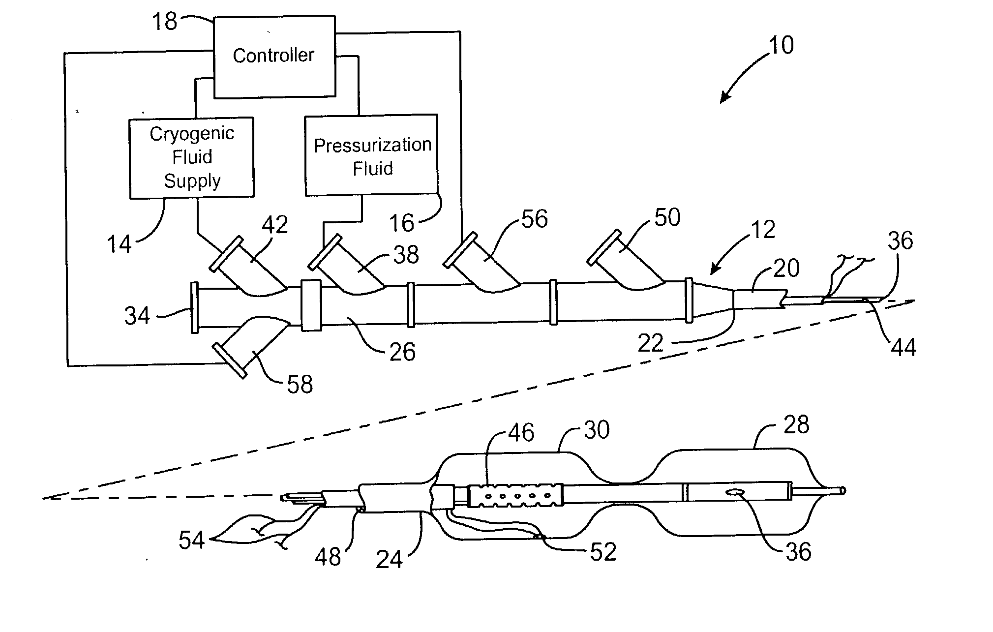
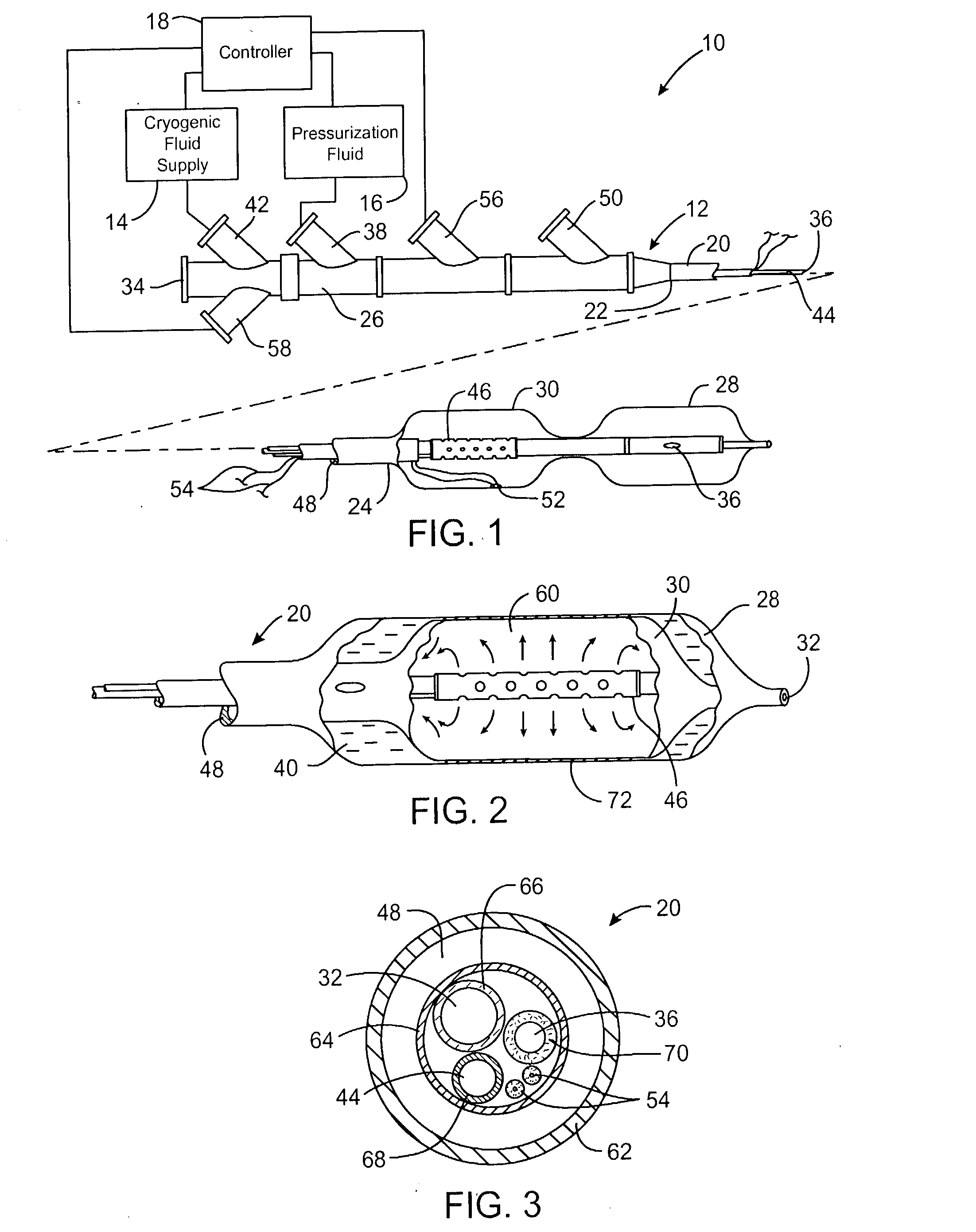
[0029] Referring now to FIG. 1, an exemplary system 10 is capable of treating a diseased vessel wall of a blood vessel using a combination of both angioplasty dilation and cryogenic cooling. In general, system 10 includes a catheter 12 coupled to a cryogenic fluid supply system 14 and an angioplasty pressurization system 16. One or both of cryogenic system 14 and pressurization system 16 may be operatively coupled to a controller 18 for coordination of cooling and dilation, as will be described in more detail hereinbelow.

[0030] Catheter 12 generally includes a catheter body 20 having a proximal end 22 and a distal end 24. A proximal housi...


PUM


Abstract

Techniques and devices for treating atherosclerotic disease use controlled cryogenic cooling, often in combination with angioplasty and / or stenting. A combination cryogenic / angioplasty catheter may cool the diseased blood vessel before, during, and / or after dilation. Controlled cooling of the vessel wall reduces actual / observed hyperplasia as compared to conventional uncooled angioplasty. Similar reductions in restenosis may be provided for other primary treatments of the blood vessel, including directional arthrectomy, rotational arthrectomy, laser angioplasty, stenting, and the like. Cooling of vessel wall tissues will often be performed through plaque, and the cooling process will preferably take the thermodynamic effects of the plaque into account.

Description

CROSS-REFERENCES TO RELATED APPLICATIONS[0001] The present application is a continuation application of U.S. patent application Ser. No. 09 / 511,191 filed on Feb. 23, 2000, which is a non-provisional of and claims the benefit of priority from U.S. Provisional Patent Application Serial No. 60 / 121,637 filed Feb. 24, 1999 (Attorney Docket No. 18468-000500); and U.S. Provisional Patent Application Serial No. 60 / 169,109 filed Dec. 6, 1999 (Attorney Docket No. 18468-000510), the full disclosure of which are incorporated herein by reference.[0002] 1. Field of the Invention[0003] The present invention relates generally to apparatus and methods for treating atherosclerotic disease. In a particular embodiment, the present invention provides a combination of controlled cryogenic cooling and balloon distention of a diseased vessel wall.[0004] A number of percutaneous intravascular procedures have been developed for treating atherosclerotic disease in a patient's vasculature. The most successful ...

Claims


Application Information

Patent Timeline
Patent Type & Authority Applications(United States)
IPC IPC(8): A61B17/22A61B18/02
CPCA61B18/02A61B2017/22001A61B2017/22002A61B2018/0262A61B2018/0022A61B2018/0212A61B2017/22062
Inventor JOYE, JAMESTATSUTANI, KRISTINEWILLIAMS, RONALDWILLIAMS, RICHARD S.
Owner BOSTON SCI SCIMED INC
Why Eureka
Try Eureka