Communication controller for an active transponder

a technology of communication controller and transponder, which is applied in the direction of radio transmission for post-communication, subscriber indirect connection, sensing record carrier, etc., can solve the problems of high battery load of transponder, very time-consuming processing of data by the transponder, and exceptional load of the battery

Inactive Publication Date: 2003-06-19
Q-FREE
View PDF3 Cites 31 Cited by
  • Summary
  • Abstract
  • Description
  • Claims
  • Application Information

AI Technical Summary

Benefits of technology

0019] The claims 6-9 concern a communications controller or useful design of it as it can be applied with advantage in connection with the method according to the invention.

Problems solved by technology

However the application of these security algorithms usually means that with this the processing of data by the transponder becomes very time consuming.
The greatest problem which consists with microcontrollers applied as communications controllers until now is that there from the relatively high clock frequency of the system clock results a relatively high load for the battery of the transponder, and this in view of the average height and the duration of the current (integral over the current pulses over the time withdrawn with the frequency of the system clock) as well as in view of the fact, that the pulse-like occuring current withdrawal represents an exceptional load for the battery.
Even if this current withdrawal does not mean so much for the life time of the components of the transponder, so a current withdrawal of such an extent and in an especially pulse-like occuring way is problematical particularly at relatively low temperatures where the internal resistance of the battery is high.
This means that such a processor is not ideal in view of the processing of data which can be processed parallel, especially not then when on the one hand processing-wise extensible actions (decoding) are necessary in the processor and on the other hand within a shortest possible duration after receipt of the input signal an output signal shall be emitted from the transponder.

Method used


Image

  • Communication controller for an active transponder
  • Communication controller for an active transponder

Examples


Embodiment Construction

[0020] In the following the invention will be described more detailed with the aid of FIGS. 1 and 2 of the drawing.

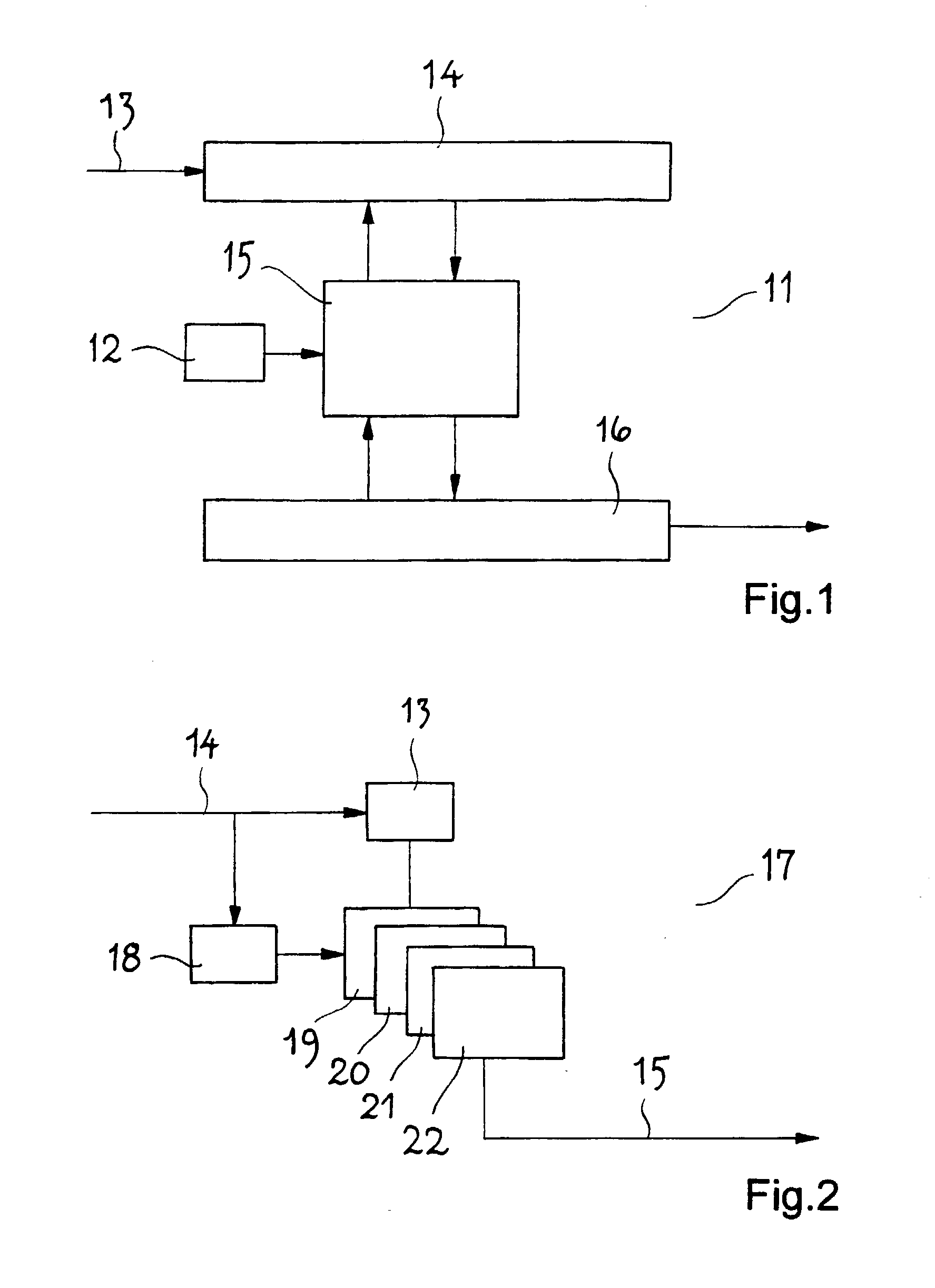
[0021] FIG. 1 shows in connection with the invention an essential part of a communications controller of a transponder according to the state-of-the-art and as a block diagram, and

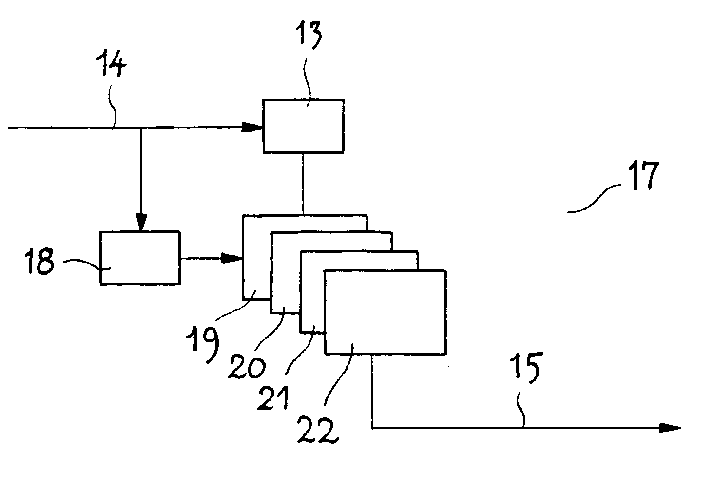
[0022] FIG. 2 shows essential parts of a communications controller as it is applied in connection with the invention and as a block diagram.

[0023] FIG. 1 shows a communication controller 11 of a transponder not shown in further detail according to the state-of-the-art. The system clock for the communications controller 1 is being delivered by an oscillator 12. Over a line 13 incoming input data are being stored in a receiving memory (buffer) 14. When the complete data sequence (data frame) is being received and stored, the processor core 15 will start the processing of the input data and prepare an answer of the transponder onto the input data. This happens with a system clock with a clock fre...


PUM


Abstract

Method and communications controller for processing of encoded information by a battery-powered active transponder. It is particularly provided for the application within a transponder system for the wireless payment of road toll, whereby the transponder over an antenna receives modulated microwave radiation of preset frequency for obtaining an input signal which is demodulated for obtaining a binary input data sequence. This is then fed to a digital processor (microcontroller) operated by a processing clock of preset clock frequency, for decoding and generating of a binary output data sequence, from which within a certain duration as an answer to the received input signal an output signal is formed, which is transmitted over the antenna of the transponder. For reducing the load of the battery of the transponder by the pulse-like occuring current demand of the processor with at the same time a relative short duration between the receiving of the input signal and the irradiating of the output signal, the data of the decoded input data sequence are parallel processed by the processor (17) with a relative low clock frequency. A plurality of processor modules (19-22) of the processor (17) which are integrated to a processing unit realizing the parallel occuring processing of data of the decoded input data sequence and are operated by a timing generator (symbol clock retrieving circuit 18) with a relative low clock frequency of the processing clock rate.

Description

[0001] The invention concerns a method according to the introductory part of claim 1 as well as a communications controller according to the introductory part of claim 6.[0002] The background of the invention is the wireless payment of charges for the use of roads (road toll) by vehicles. Systems provided for this purpose have been delivered by the Q-Free ASA company since many years. Nowadays these systems are used in Norway and are well known under the term "Q-Free-box". In this connection the term "box" is related to the module of this system attached to an individual vehicle, that is to say to a so-called transponder. This transponder receives data from a main station of the transponder system and as an answer on this transmitts individual data back to the roadside.[0003] Meanwhile the technological development in this field has turned to transponders which--contrary to transponders formerly used in this field--are being operated not passive, but active and for the operation of ...

Claims


Application Information

Patent Timeline
Patent Type & Authority Applications(United States)
IPC IPC(8): G06K7/00H04B1/59G06K19/07G07B15/06H04B7/26
CPCG06K7/0008G07B15/063G06K19/0723G06K19/0701
Inventor SAEGROV, ATLE
Owner Q-FREE
Why Eureka
Try Eureka