

Polishing composition
a technology of composition and polishing, applied in the field of polishing composition, can solve the problems of poor balance between mechanical components and chemical components, microprotusions or fine pits, and volumetric removal of substrate surfaces, and achieve the effect of low haze and high polishing removal ra
- Summary
- Abstract
- Description
- Claims
- Application Information
AI Technical Summary
Benefits of technology
Problems solved by technology
Method used
Image

Examples
example 1
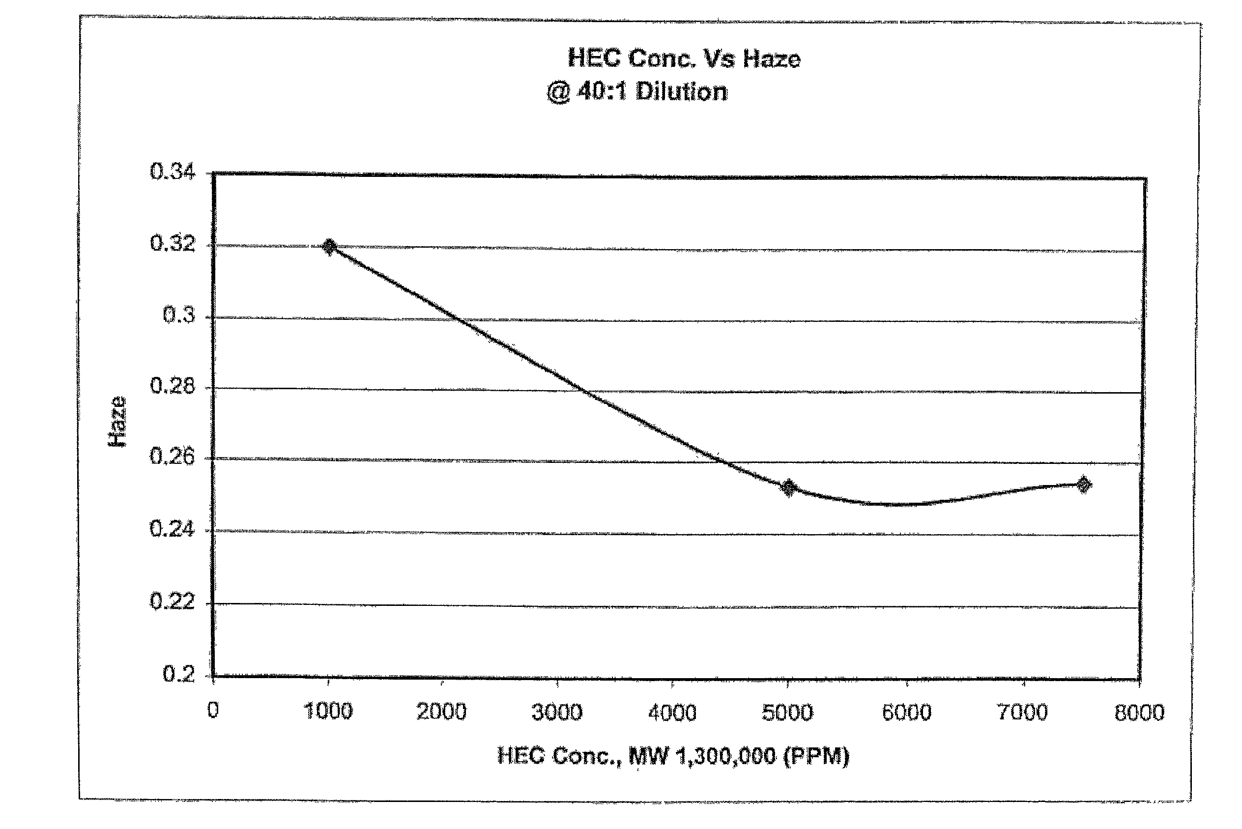
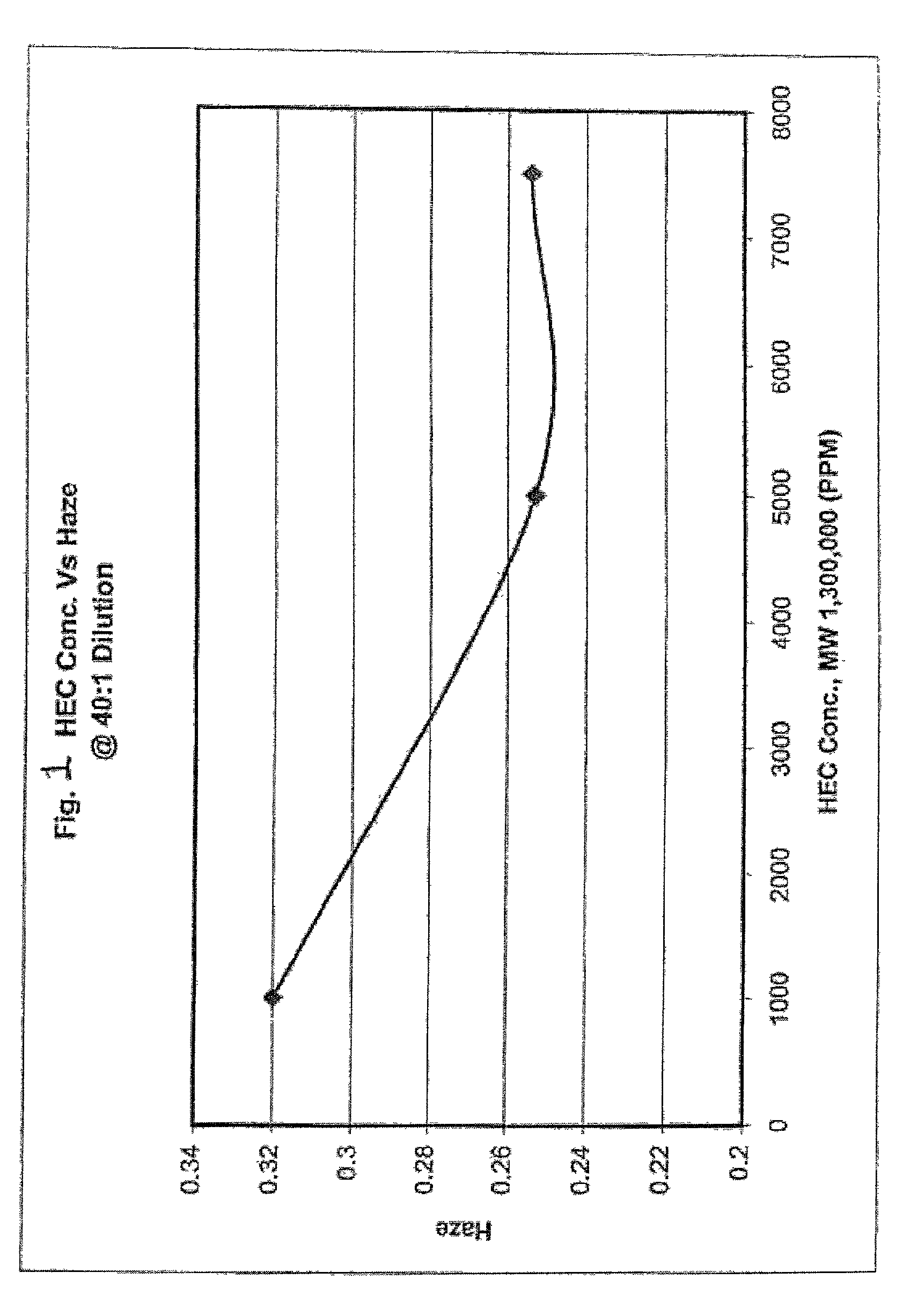
[0034] Sample compositions, in accordance with the present invention, were tested at varying concentrations of hydroxyethylcellulose. The concentrations and properties of the other materials in the composition were kept the same for each sample composition. Table I lists formulations tested at a 40:1 dilution. FIG. 1 illustrates the effect hydroxyethylcellulose has on haze at varying concentrations of hydroxyethylcellulose for slurries at a 40:1 dilution.
1TABLE I HEC concentration formulations (40:1 dilution) Target HEC HEC NH.sub.4OH Target Slurry Abrasive (MW) Conc. Conc. Dilution RPTA-0113 4.00% 1,300,000 0.50% 0.500% 40:1 RPTA-0114 4.00% 1,300,000 0.75% 0.500% 40:1 RPTA-0119 4.00% 1,300,000 0.10% 0.500% 40:1
example 2
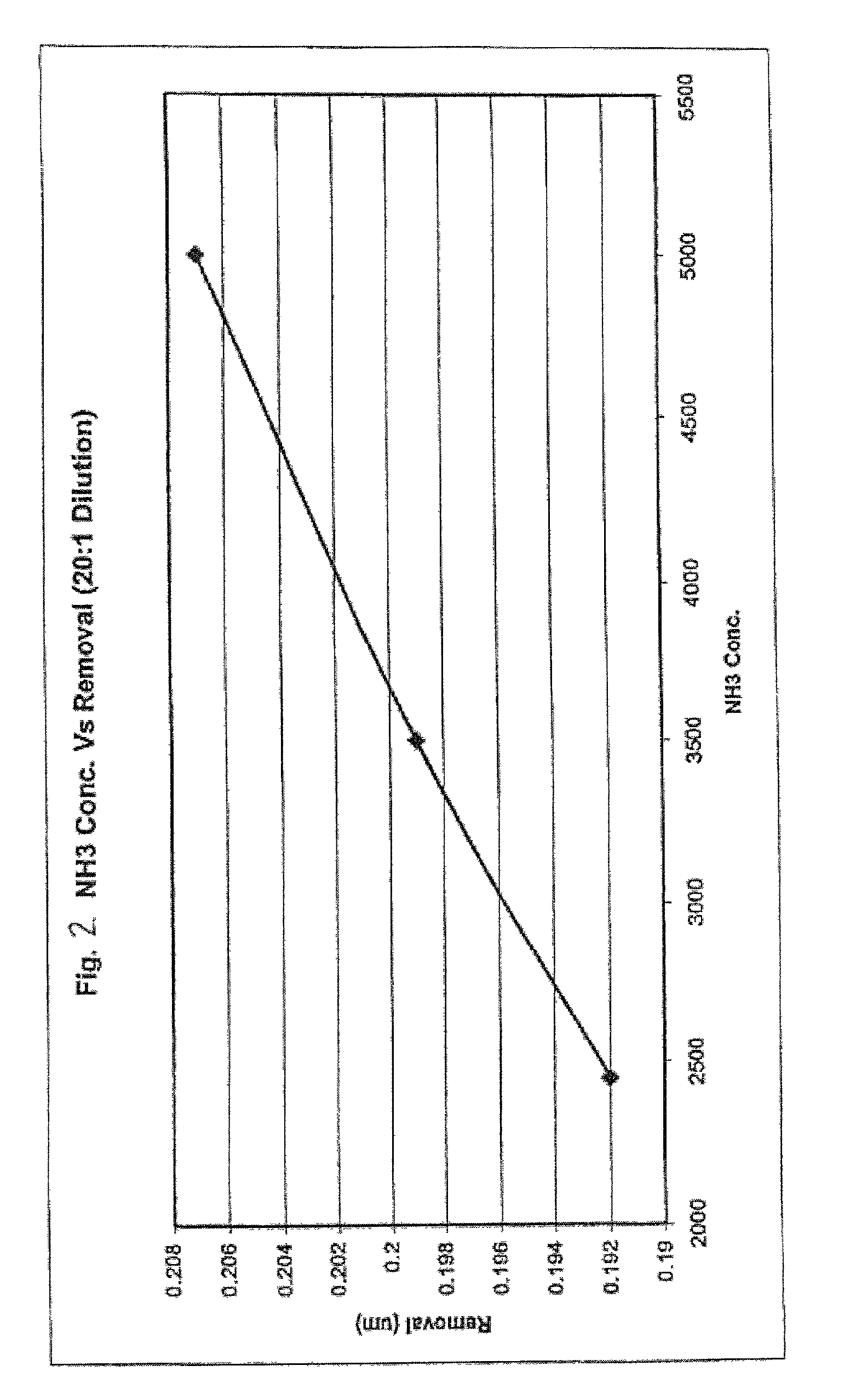
[0035] Sample compositions, in accordance with the present invention, were tested at varying concentrations of ammonia. The concentrations and properties of the other materials in the composition were kept the same for each sample composition. Table II lists formulations tested at a 20:1 dilution. FIG. 2 illustrates how the removal rate is affected for varying concentrations of ammonia for a slurry with 20:1 dilution.
2TABLE II NH.sub.4OH Concentration Testing Formulations. Target HEC HEC NH.sub.4OH Target Slurry Abrasive (MW) Conc. Conc. Dilution RPTA-0101 9.50% 1,300,000 0.25% 0.245% 20:1 RPTA-0107 9.50% 1,300,000 0.25% 0.500% 20:1 RPTA-0111 9.50% 1,300,000 0.25% 0.350% 20:1
example 3
[0036] Sample compositions, in accordance with the present invention, were tested at varying concentrations of tetra methyl ammonium hydroxide. The concentrations and properties of the other materials in the composition were kept the same for each sample composition. Table Ill lists TMAH formulations tested at both 20:1 and 40:1 dilutions. Tables IV and V show the polishing results obtained with the formulations listed in Table III. All testing was performed on the Strausbaugh 6EC. The 20:1 dilution Table III formulations were polished for 8 and 10 minutes minutes, and the 40:1 dilution Table III formualtions were polished for 6 minutes under the same polishing parameters. The pad used for the formulation screening was a SPM3100 pad. FIG. 3 illustrates how the removal rate decreases as the concentration of TMAH is increased. Tables IV and V show decreasing removal rate and haze with increasing TMAH.
3TABLE III TMAH testing formulations. Target HEC HEC TMAH NH.sub.4OH Target Slurry Ab...
PUM
| Property | Measurement | Unit |
|---|---|---|
| size | aaaaa | aaaaa |
| particle size | aaaaa | aaaaa |
| particle size | aaaaa | aaaaa |
Abstract
Description
Claims
Application Information