Power servo-loop, an RF signal amplifier circuit, and an RF signal transmitter fitted with such a circuit

Inactive Publication Date: 2003-08-21
DRNC HLDG INC
View PDF3 Cites 6 Cited by
  • Summary
  • Abstract
  • Description
  • Claims
  • Application Information

AI Technical Summary

Benefits of technology

0009] The object of the invention is to provide a servo-loop having a detect

Problems solved by technology

Unfortunately, it can happen that an interference RF signal travels through the transmitter in the direction opposite to the propagation direction of the output signal.
This interference signal also has a fraction of its power taken off via the coupling means of the detection circuit, which fraction is added to the taken-off fraction of the output signal and leads to distortion such that the detection voltage is no longer a true image of the o

Method used


Image

  • Power servo-loop, an RF signal amplifier circuit, and an RF signal transmitter fitted with such a circuit
  • Power servo-loop, an RF signal amplifier circuit, and an RF signal transmitter fitted with such a circuit
  • Power servo-loop, an RF signal amplifier circuit, and an RF signal transmitter fitted with such a circuit

Examples


Embodiment Construction

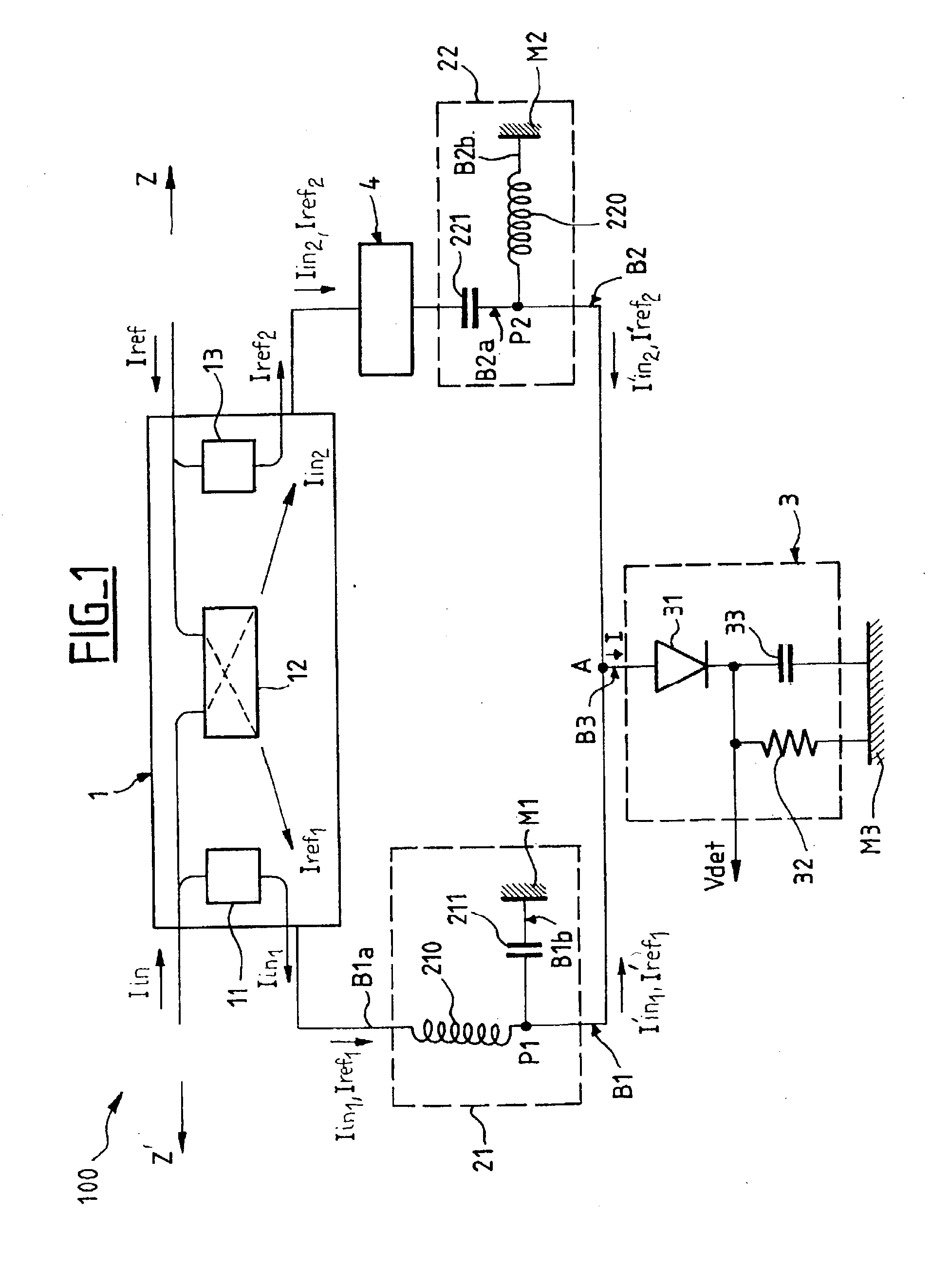
[0030] FIG. 1 shows an embodiment of a detection circuit 100 for a power loop of the invention.

[0031] The detection circuit 100 comprises:

[0032] coupling means 1 of the hybrid directional coupler type having phase shifter means 11, 12, 13 for taking off RF signals weighted by a respective appropriate takeoff gain factors G.sub.1, G.sub.2, G.sub.3, and for phase shifting them by .DELTA..phi..sub.1, .DELTA..phi..sub.2, .DELTA..phi..sub.3, respectively;

[0033] first and second output branches B1 and B2 interconnected at an interconnection point A to a "detection" branch B3 comprising a detection unit 3 made up of a rectifier diode 31 connected to a resistor 32 and a capacitor 33 in parallel and connected to a ground plane M3; and

[0034] detection control means comprising:

[0035] first phase shifter means 21 inserted in the first output branch B1 to phase shift RF signals by -.DELTA..phi..sub.0s, and second phase shifter means 22 inserted in the second output branch B2 to phase shift RF si...


PUM


Abstract

The present invention relates to a power servo-loop in particular for controlling a power amplifier, the loop comprising a detection circuit (100) having coupling means (1) for taking off RF signals, and a detection unit (400) for delivering a detection signal (Vdet) partially representative of a first RF signal taken off by the coupling means. The detection circuit of the invention comprises, between the coupling means and the detection unit, detection control means (21, 22, 4) for substantially eliminating an "interfering" second RF signal also taken off by the coupling means, such that the detection signal is entirely representative of the first RF signal.

Description

[0001] The present invention relates to the field of transmitting radio frequency (RF) signals, and it relates more particularly to a power servo-loop, in particular for controlling a power amplifier.[0002] In known manner, in a telecommunications system in which an RF signal transmitter is sending to a receiver of such signals, it is necessary to ensure maximum quality of service. For example, when transmitting digital signals, this condition requires the binary error rate to remain at all times below a specified rate. To satisfy this condition on reception, it is necessary to ensure that the received signal-to-noise ratio is at all times above a predetermined value.[0003] In order to make it possible to raise the power of the RF signals for transmission, the transmitter is provided with a power amplifier. By way of example, for a call between a mobile terminal and a base station in a cellular network of the GSM (global system for mobile communications) type, the purpose of the pow...

Claims


Application Information

Patent Timeline
IPC IPC(8): H03F1/34H04B1/04H03G3/30
CPCH03G3/3036H03F1/34
Inventor KOLODZIEJ, PIERREPOULIQUEN, MIKAEL
Owner DRNC HLDG INC
Why Eureka
Try Eureka