
Beam bending apparatus and method of manufacture

a beam bending and beam technology, applied in the field of optical devices, can solve the problems of index gradient being produced by an ion exchange process that is both time-consuming and expensive, refraction at these surfaces, and each approach has its own set of limitations

Inactive Publication Date: 2003-09-04
CORNING INC
View PDF21 Cites 48 Cited by
  • Summary
  • Abstract
  • Description
  • Claims
  • Application Information

AI Technical Summary

Benefits of technology

[0017] The beam bending apparatus of the present invention results in a number of advantages over other mode-transforming devices known in the art. In one respect, since a mode-transforming lens may be formed directly on a GRIN-fiber lens, the geometric shape and / or size of the mode field of an optical signal may be altered by the mode-transforming lens, while the focusing of the altered optical signal may be largely performed by the GRIN-fiber lens. As a result, the wavefront of the optical signal may be better matched to that of the optical component or other waveguide to which the optical signal is coupled. Accordingly, coupling losses are minimized and phasefront aberrations are reduced. The beam bending apparatus of the present invention may also be designed to provide for a greater range of operative working distances. As a result of these and other advantages, coupling efficiencies are greatly improved.
[0018] In addition to these advantages, the GRIN-fiber lens itself provides a number of advantages in the manufacture of the present invention. As mentioned hereinabove, GRIN-fiber lenses are preferably high silica containing structures preferably made by conventional multi-mode fiber manufacturing processes. Because GRIN-fiber lenses are made by telecommunication fiber manufacturing techniques, GRIN-fiber lenses manufactured in accordance with the present invention may be drawn to the desired dimensions with a high degree of accuracy. Generally speaking, GRIN-fiber lenses may be drawn having an outside diameter ranging from about 25.0 microns to about 1000.0 microns. More preferably, such GRIN-fiber lenses may be drawn such that they have outside diameters ranging from about 50.0 microns to about 500.0 microns. More preferably such GRIN-fiber lenses may have an outside diameter of between about 75.0 microns to about 250.0 microns. In addition, since GRIN-fiber lenses may be drawn using traditional fiber drawing equipment, large diameter rods or blanks may be manufactured and thereafter drawn to long lengths (up to several kilometers) of fiber while maintaining the material properties, such as, but not limited to, the core to clad ratio of the original large diameter rod, thus making manufacturing and splicing easier. Accordingly, the desired refractive index profile, among other characteristics, of the GRIN-fiber lens may be designed into the larger rod or blank which provides for precision submicron control over the resulting GRIN- fiber lens optical properties.
[0019] In addition to these advantages, GRIN-fiber lenses may be fabricated in accordance with the present invention such that they have the predetermined material characteristics for more than one mode-transforming application. Since a mode-transforming lens may be formed on the GRIN-fiber lens or on a coreless spacer rod or fiber affixed to the GRIN-fiber lens, rather than the pigtail fiber itself, GRIN-fiber lenses and coreless spacer rods having the same length, formed of the same materials, having the same aspect ratios, and having the same cross-sectional areas may be affixed to pigtail fibers having different characteristics and / or mode fields. Thereafter, each GRIN-fiber lens and / or coreless rod may be altered, by cleaving to the appropriate length, for example, to provide the required mode field transforming functionality required for the particular fiber pigtail to which each GRIN-fiber lens and / or spacer rod is affixed. As will be described in greater detail, this may preferably be accomplished by cleaving or otherwise cutting each GRIN-fiber lens and / or spacer rod to the desired length and configuring the cut end of each GRIN- fiber lens and / or rod to have the desired optical signal altering properties.
[0022] The beam bending apparatus of the present invention provides additional advantages for optical assemblies and other packaging arrangements. The beam bending apparatus of the present invention provides for working distances as large as about twenty (20.0) microns or more, which is significantly larger than working distances provided by anamorphic and other mode-transforming apparatus known in the art. As a result, coupling to a laser diode or other semiconductor device with low loss is facilitated due in part to the relaxed alignment tolerances between the apparatus and the semiconductor device.
[0023] All of the above-mentioned aspects of the present invention provide for large scale production of GRIN-fiber lenses and / or spacer rods, which in turn facilitates ease of manufacture, reduced costs associated with the manufacturing process, and greater economies of scale. The apparatus of the present invention may be constructed such that the mode field of an optical signal passing therethrough may be changed from an elliptical mode field to a circular mode field, from a circular mode field to an elliptical mode field, from a mode field having one ellipticity to a mode field having a different ellipticity, or from one mode field to another mode field having the same shape but a different size. Moreover, the apparatus of the present invention may be designed such that it may alter the mode field of an optical signal passing therethrough, in either direction.
[0024] Additional features and advantages of the invention will be set forth in the detailed description which follows and in part will be readily apparent to those skilled in the art from that description or recognized by practicing the invention as described herein.

Problems solved by technology

Accordingly, unlike conventional lenses, GRIN-rod lenses have planar input and output surfaces making refraction at these surfaces unnecessary.
The index gradient is typically produced by an ion-exchange process that is both time-consuming and expensive.
Each approach does, however, have its own set of limitations.
Likewise, while anamorphic fiber lenses readily facilitate the changing of the geometric shape of the optical signal or beam passing through them, the range of available working distances for anamorphic lens applications is somewhat limited.
Accordingly, if suitable working distances are not available for particular applications, coupling losses may be significant, thereby making many coupling applications impractical.
Without the aid of mirrors, or other optical devices and structures, the above-mentioned known devices are poorly adapted for, "off-line" coupling applications, i.e., those coupling applications where an optical signal to be coupled is traveling along a path that is not co-linear with the optical axis of the device to which the optical signal is to be coupled.
Failure to do so may result in aberrations, which are the result of constructive or destructive interference with coupling efficiency.
This is very time consuming and does not facilitate the efficient manufacture of mode field coupling assemblies.

Method used


Image

  • Beam bending apparatus and method of manufacture
  • Beam bending apparatus and method of manufacture
  • Beam bending apparatus and method of manufacture

Examples


Embodiment Construction

[0081] An example of an off-line or non-in-line beam bending apparatus and optical assembly in accordance with the above-mentioned embodiments of the present invention will now be described.

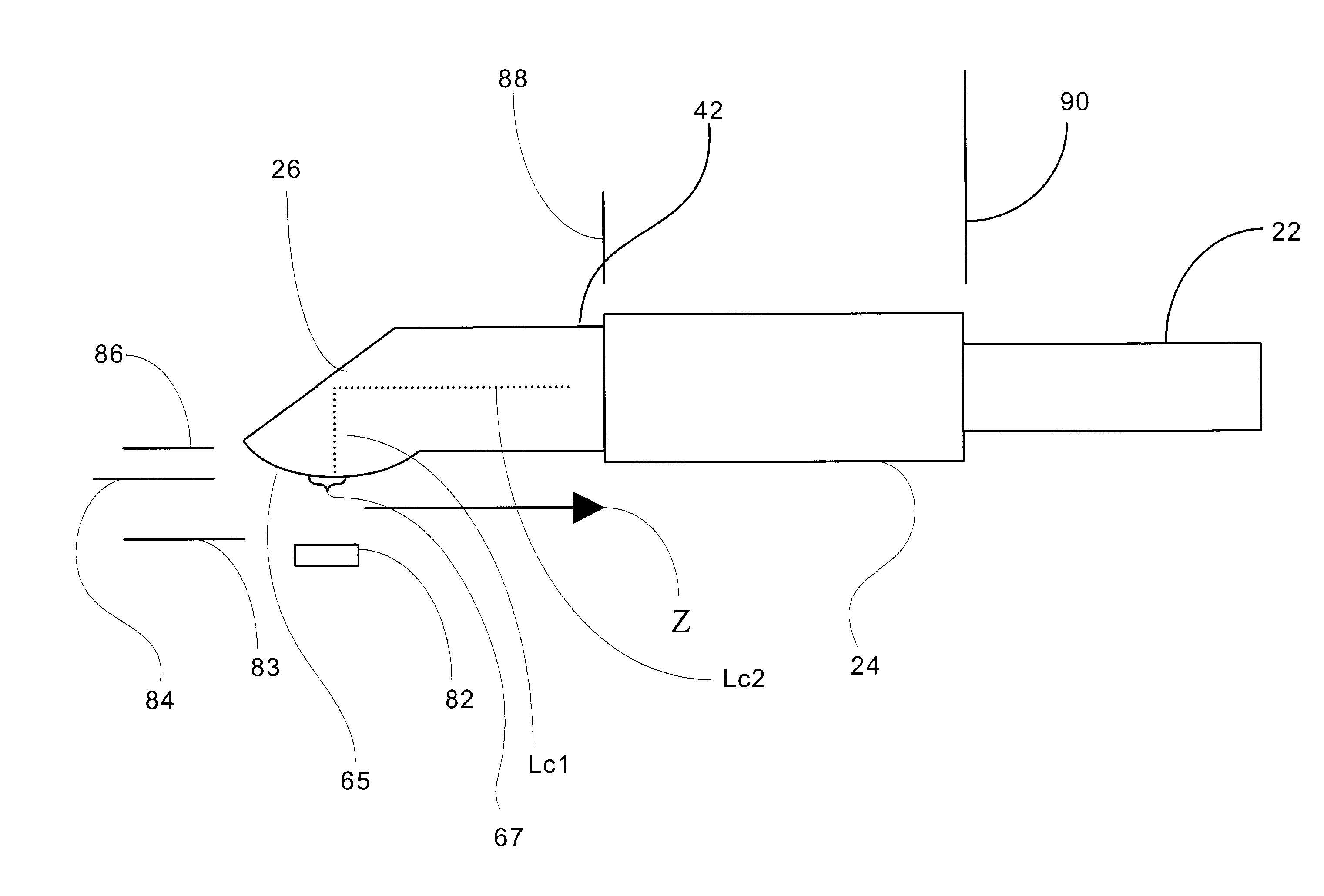
[0082] An exemplary off-line beam bending apparatus 80, including a ball lens 65 having a biconic curved surface 67 and a beveled reflective surface 26, is shown schematically in FIG. 8 with reference to the variables described below. The exemplary multi-lens apparatus includes a source 82 of an optical signal, in this case a laser diode capable of emitting a signal at an operating wavelength `wav`; Mode-field-diameter (MFD) in the x-direction (vertical direction) of wx0(.mu.m), and MFD in the y-direction of wy0 (.mu.m). The beam from the source 82 propagates through a medium (most commonly air) of index (nl) for a distance (z) before falling on a curved surface 67 with radii of curvature of (RLx) (.mu.m) in the x-direction and (Rly) (.mu.m) in the y-direction that is formed on a spacer rod 42 ha...


PUM


Abstract

An apparatus for altering the mode field of an optical signal is disclosed. The apparatus includes a GRIN-fiber lens and a reflective surface disposed at one end of the GRIN-fiber lens, the reflective surface configured to cooperate with the GRIN-fiber lens to redirect the path of the optical signal directed against the reflective surface. A method of manufacturing an apparatus for altering the mode field of an optical signal and an optical assembly are also disclosed.

Description

[0001] This application claims the benefit of U.S. Provisional Application Serial No. 60 / 361,787, filed Mar. 4, 2002, and entitled, "Beam Altering Fiber Lens Device and Method of Manufacture," which is hereby incorporated herein by reference.BACKGROUND OF INVENTION[0002] 1. Field of the Invention[0003] The present invention relates generally to an optical device for non-in-line mode field interconnections, and more particularly, to a mode-transforming apparatus configured to facilitate high efficiency coupling of optical signals passed between such an apparatus and an optical component and / or other waveguide having a different mode field.[0004] While the present invention is subject to a wide range of applications, it is particularly well suited for coupling sources of elliptically-shaped optical signals, such as laser diodes and semiconductor waveguides, to optical fibers having circularly symmetric mode fields.[0005] 2. Technical Background[0006] Coupling optical signals passed be...

Claims


Application Information

Patent Timeline
Patent Type & Authority Applications(United States)
IPC IPC(8): G02B6/02G02B6/255G02B6/26G02B6/30G02B6/32G02B6/42H01S5/022
CPCG02B6/2552G02B6/262G02B6/30G02B6/4214G02B6/4202G02B6/4203G02B6/4206G02B6/32
Inventor BHAGAVATULA, VENKATA A.SHASHIDHAR, NAGARAJAHIMMELREICH, JOHN
Owner CORNING INC
Learn More