

Secondary battery and method of producing the same
- Summary
- Abstract
- Description
- Claims
- Application Information
AI Technical Summary
Benefits of technology
Problems solved by technology
Method used
Image

Examples
examples 6 to 10
[0131] Batteries were produced in the same manner as in Example 1, except that in the second step, lithium phosphate as an ion conductive material was employed in place of the electron conductive material (platinum) included in the positive electrode. More specifically, in the second step, a target comprising lithium phosphate was used in place of the target comprising platinum. Then, lithium phosphate was sputtered, simultaneously with lithium cobaltate, thereby producing a positive electrode layer containing the ion conductive material.
[0132] Additionally, the rf power ratios in the rf magnetron sputter process were changed such that the volume percentages of lithium phosphate in the positive electrode layers were 2 vol % (Example 6), 5 vol % (Example 7), 25 vol % (Example 8), 50 vol % (Example 9) and 60 vol % (Example 10), respectively.
[0133] The thicknesses of the positive electrode layers of the batteries were 4.1 .mu.m (Example 6), 4.2 .mu.m (Example 7), 5.3 .mu.m (Example 8),...
examples 11 to 15
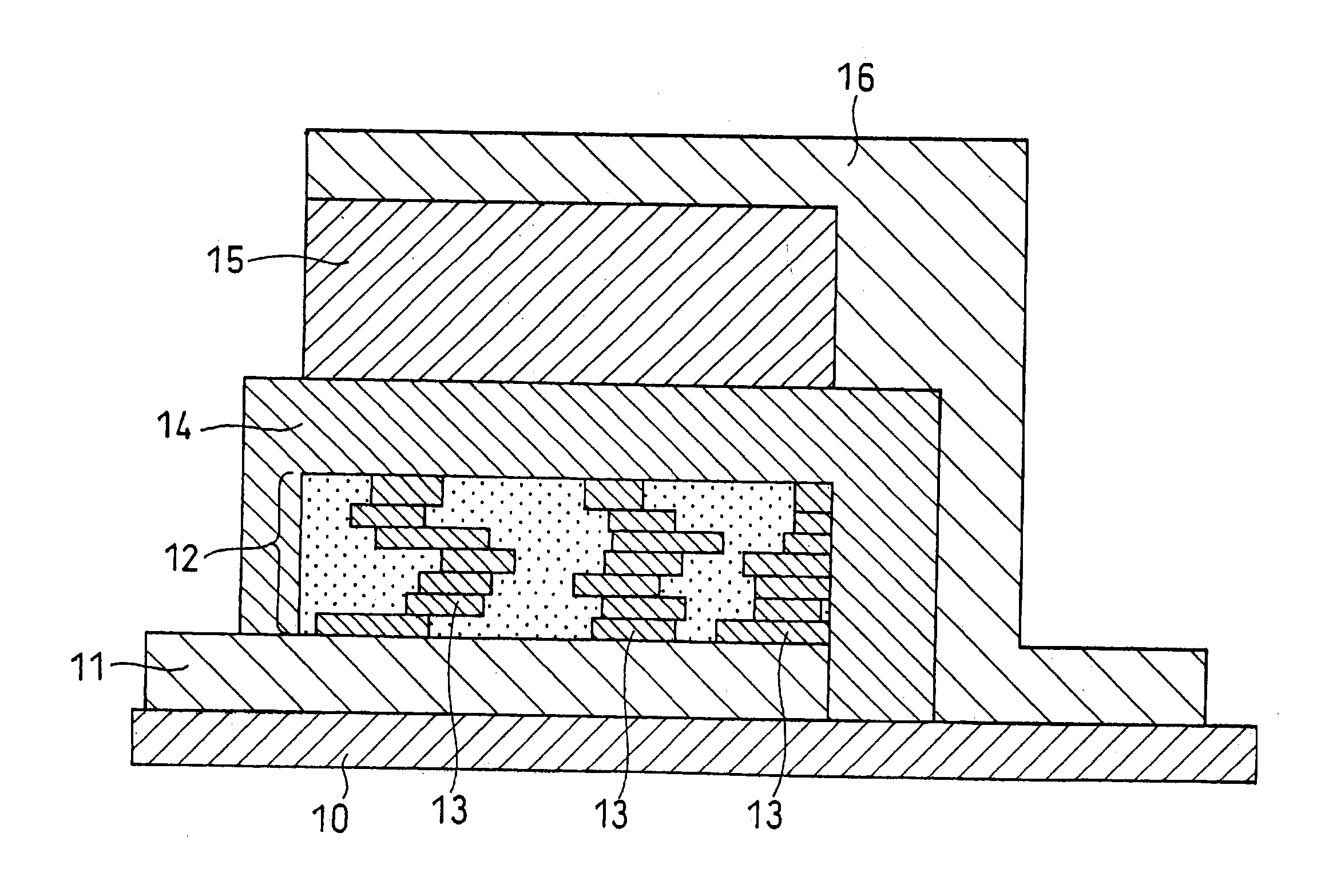
[0134] Batteries were produced in the same manner as in Example 1, except that in the second step, both the electron conductive material (platinum) and the ion conductive material (lithium phosphate) were included in the positive electrode layer. More specifically, in the second step, a target comprising lithium cobaltate, a target comprising platinum and a target comprising lithium phosphate were used. Then, platinum and lithium phosphate were sputtered, simultaneously with lithium cobaltate, thereby producing a positive electrode layer containing the electron conductive material and the ion conductive material.
[0135] The rf power ratios in the rf magnetron sputter process were changed such that the total volume percentages of platinum and lithium phosphate in the positive electrode layers were 2 vol % (Example 11), 5 vol % (Example 12), 25 vol % (Example 13), 50 vol % (Example 14) and 60 vol % (Example 15), respectively. The volume ratio of platinum and lithium phosphate included ...
examples 16 to 20
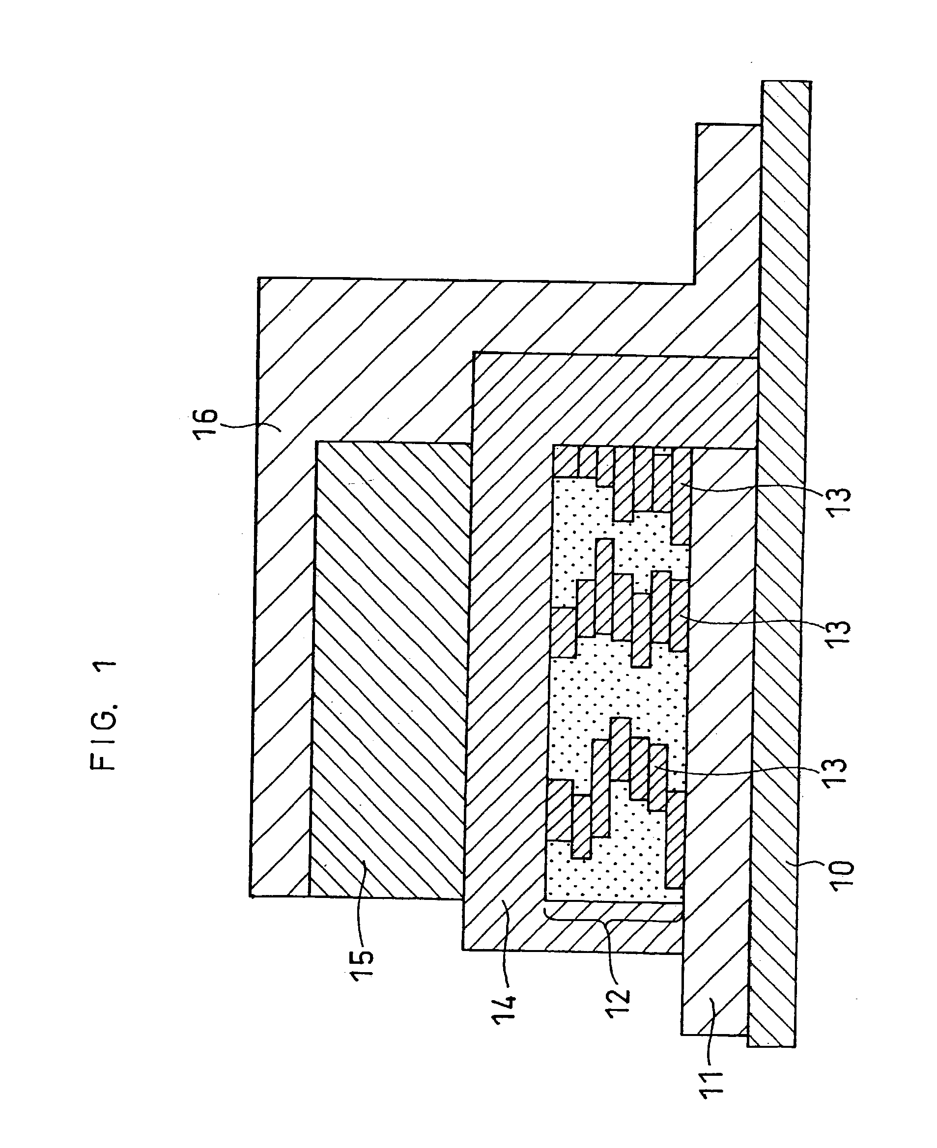
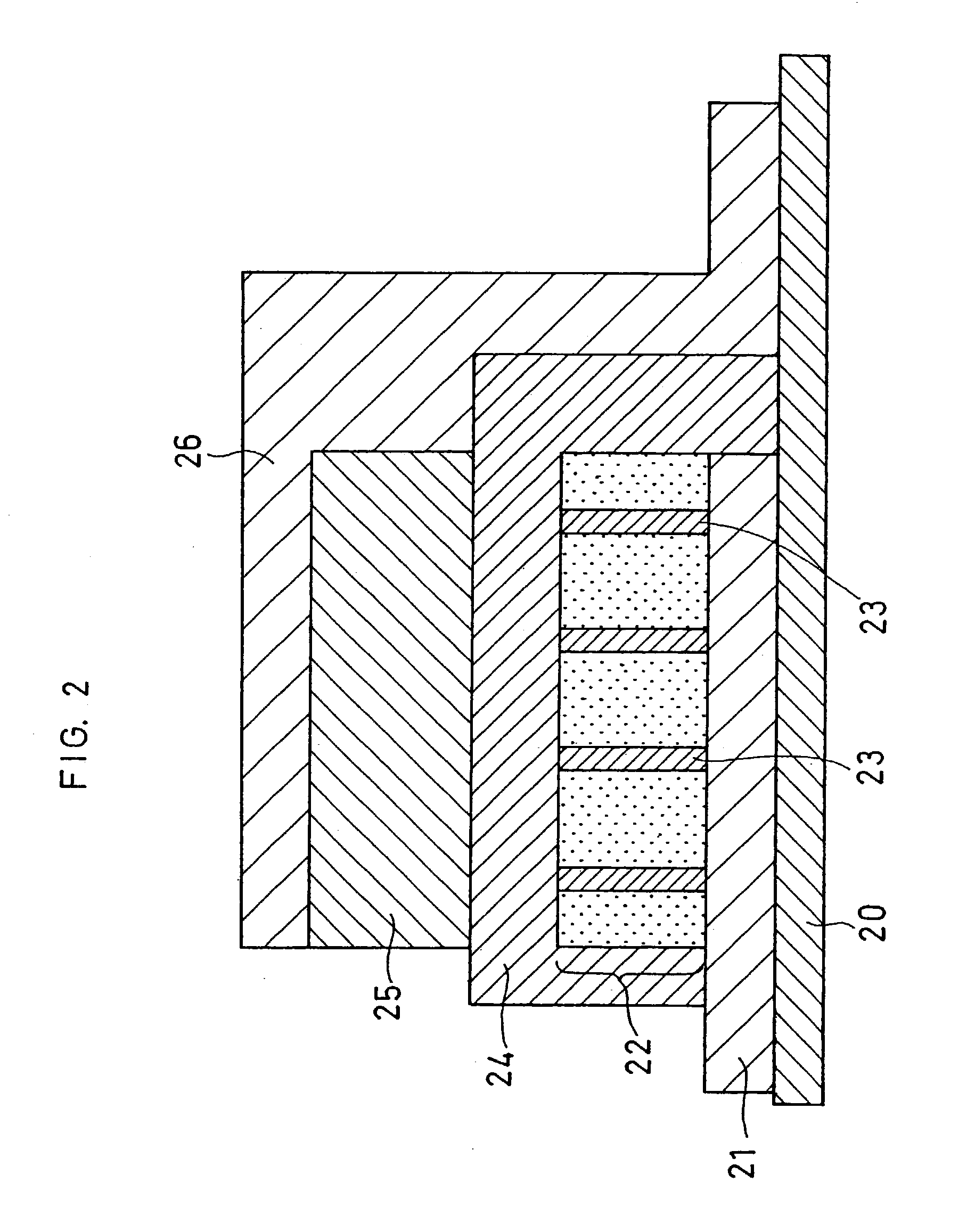
[0137] Batteries were produced in the same manner as in Example 1, except that in the second step, lithium phosphate as an ion conductive material was employed in place of the electron conductive material (platinum) included in the positive electrode, and lithium cobaltate and lithium phosphate were alternately sputtered rather than that lithium phosphate was sputtered simultaneously with lithium cobaltate.
[0138] Herein, lithium cobaltate was sputtered at the beginning, and thereafter, lithium phosphate and lithium cobaltate were alternately sputtered, and lithium phosphate was sputtered at the end. In addition, the materials to be spattered were switched when the material being sputtered was deposited until the thickness thereof became 1% of that of the positive electrode layer.
[0139] Additionally, the rf power ratios in the rf magnetron sputter process were changed such that the volume percentages of lithium phosphate in the positive electrode layers were 2 vol % (Example 16), 5 v...
PUM
| Property | Measurement | Unit |
|---|---|---|
| Fraction | aaaaa | aaaaa |
| Fraction | aaaaa | aaaaa |
| Fraction | aaaaa | aaaaa |
Abstract
Description
Claims
Application Information