
Moving object detection method

Inactive Publication Date: 2003-10-30
JAPAN AEROSPACE EXPLORATION AGENCY
View PDF7 Cites 47 Cited by
  • Summary
  • Abstract
  • Description
  • Claims
  • Application Information

AI Technical Summary

Benefits of technology

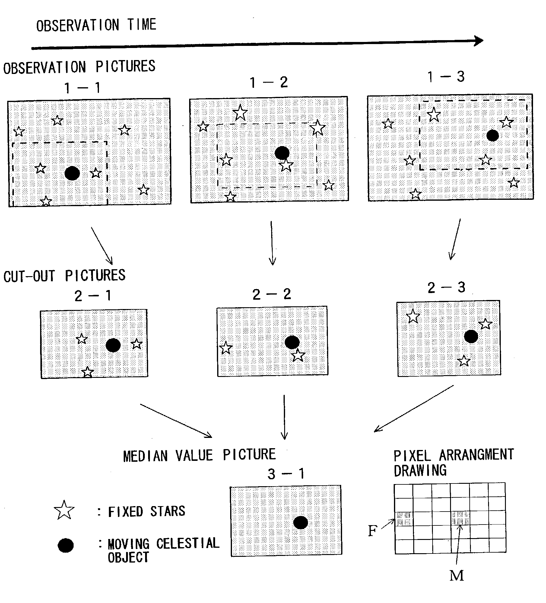
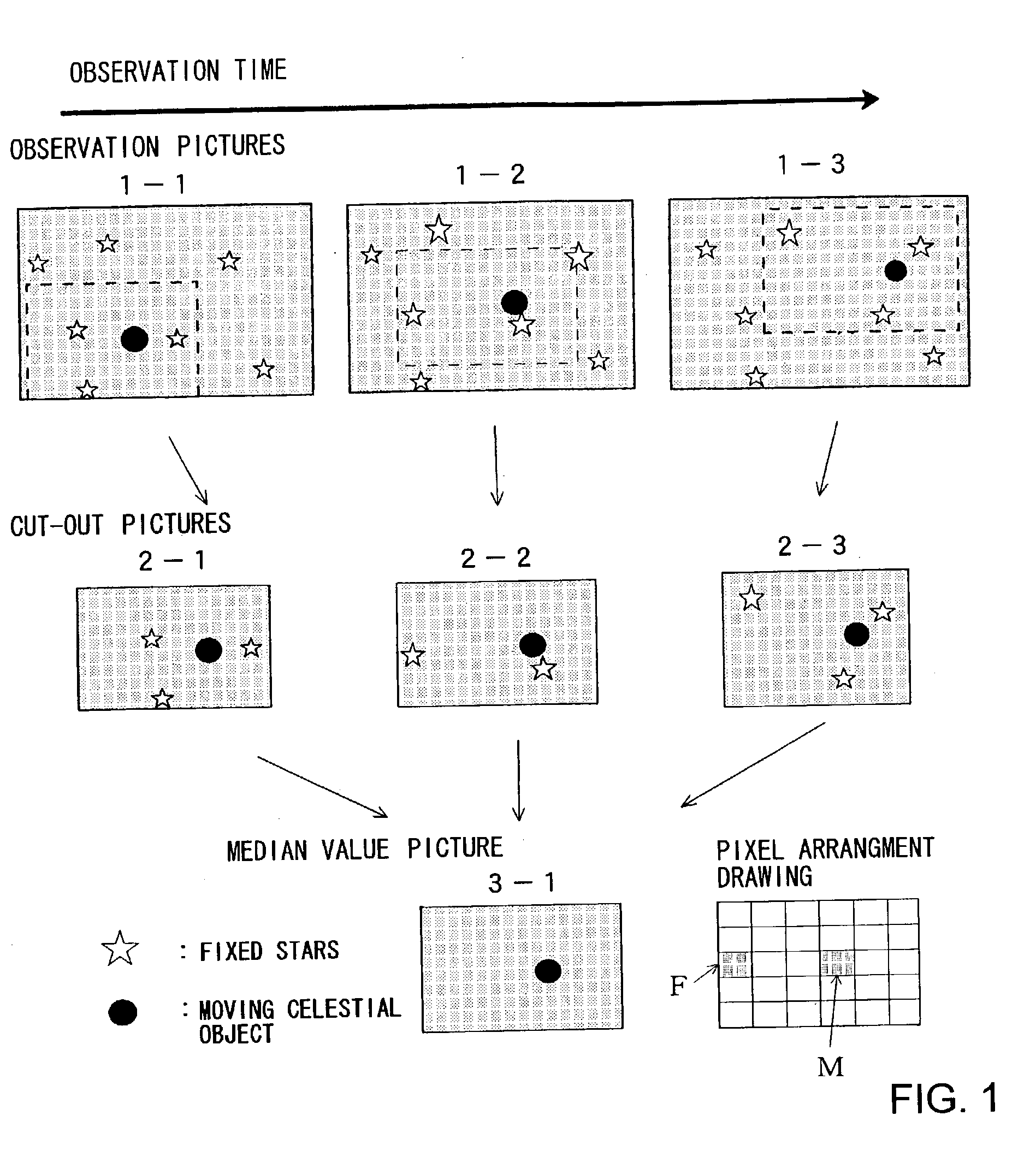
[0012] With the present invention, when median value pictures are created by using cut-out pictures matching the movement of a virtual moving object from a plurality of observation pictures, the median value pictures with a reduced effect of pixel values indicating singular values are created by eliminating in advance the images of large bright light sources (in the case of celestial objects, including the central portions of fixed stars and peripheral portions thereof), dark fixed stars, and pixels that output no pixel values and were lost when median values are calculated, the effects of the images of large bright light sources (in the case of celestial objects, fixed stars), dark pictures, and the lost pixels that output no pixel values, which serve as noise for moving object detection, are effectively eliminated and a moving object that is too dark to be caught with a single observation picture be effectively detected. Conducting such an image processing for removing singular values makes it possible to raise the detection limit of moving bodies and to reduce greatly the ratio of erroneous detection.
[0019] This method will contribute significantly to the discovery and orbital determination of space debris having a diameter ranging from several centimeters to several tens centimeters, which is difficult to detect at present and which could seriously harm operating man-made satellites and the international space station currently under construction. It will also enable the early-stage discovery of asteroids and comets having a diameter ranging between several hundred meters and one kilometer that in the event of a collision with Earth would affect human activity and even put the very survival of the human race at risk.

Problems solved by technology

As a result, while the probability of locating a moving celestial object has increased, the number of fixed stars, which amount to noise insofar as moving celestial object detection is concerned, has also increased, and now number in the several tens of thousands.
Detecting moving celestial objects in the midst of this large background of noise is extremely difficult.
Moreover, because a moving celestial object moves in the pictures, sufficient results cannot be obtained when a dark moving celestial object is to be detected, even when using a fixed star observation technology in which the exposure period is lengthened so that the light from a celestial object is accumulated at a fixed position in the picture.
However, because the bright light sources (fixed stars) have a spread in the form of a central portion and peripheral portion thereof on the pictures and there is also a loss of pixels which do not return the pixel values and pictures of dark fixed stars, images of those stars produce a significant effect on calculation of median values of pixel values of cut-out pictures.
This method will contribute significantly to the discovery and orbital determination of space debris having a diameter ranging from several centimeters to several tens centimeters, which is difficult to detect at present and which could seriously harm operating man-made satellites and the international space station currently under construction.

Method used


Image

  • Moving object detection method
  • Moving object detection method
  • Moving object detection method

Examples


Embodiment Construction

[0058] FIG. 5 is a drawing showing an example of the picture obtained using the moving celestial object detection method pertaining to the present invention.

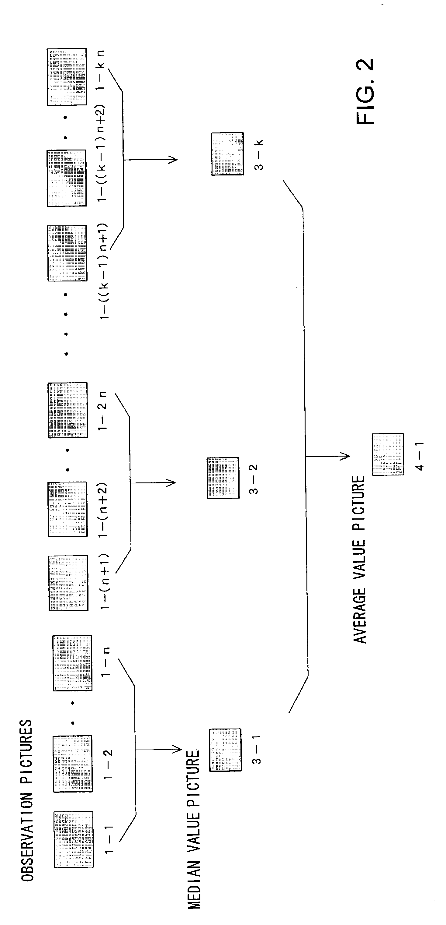
[0059] In order to detect a satellite or piece of debris having a geosynchronous orbit, a CCD camera having a 3 cm.times.3 cm image area was mounted to a wide-angle telescope having a diameter of 50 cm and an F-value of 2.0, and the geosynchronous orbital region was continuously captured in thirty pictures in fixed star pursuit mode with an exposure time of 2 seconds and an exposure interval of 13 seconds. In fixed star pursuit mode, the movement of a celestial object in a geosynchronous orbit consists of eastward movement of approximately 15" per second. As a result, a region corresponding to this movement was cut out from each picture, and first, three median value pictures were created from 10 pictures each, and an average value picture was created from these three median value pictures.

[0060] FIG. 5-A is a picture cut out fr...


PUM


Abstract

From a plurality of pictures 1-1 through 1-3 captured at successive time intervals, pictures 2-1 through 2-3 of regions determined in accordance with the movement of the celestial object are cut out. By deriving median values in regard to the same pixels in each of the cut-out pictures 2-1 through 2-3, a median value picture 3-1 is created. By deriving median values, the influence of large numbers of fixed starts that hinder the detection of the moving celestial object that moves in the cut-out pictures is eliminated, and only the moving celestial object is permitted to remain. When deriving median value, pixel values indicating singular values are eliminated in advance, so that the effects of the images of large bright light sources and the lost pixels that output no pixel values are effectively reduced. Further, when an average value picture is created using a plurality of median value pictures previously obtained, the detection limit increases and a dark moving celestial object that cannot be detected using a single observation picture can be extracted.

Description

[0001] 1. Field of the Invention[0002] The present invention relates to a method for detecting a moving object (a moving celestial object such as a man-made celestial object, space debris, an asteroid, a comet and the like), and relates in particular to a moving object detection method for (1) monitoring a man-made celestial object such as a small, dark man-made satellite, etc., and determining the orbit thereof, (2) discovering space debris that could cause major harm to industry if it collided with an operating man-made satellite or the like, and determining the orbit thereof, or (3) discovering at an early stage an asteroid or comet that could, in the event of a collision with Earth, have a serious impact on human industrial activities, or on the very existence of the human race, and determining the orbit thereof.[0003] 2. Description of the Related Art[0004] FIG. 8 is a drawing to explain the conventional method for detecting a moving celestial object. The observation pictures (...

Claims


Application Information

Patent Timeline
IPC IPC(8): B64G3/00G09B27/00G06T1/00G06T3/00G06T5/50G06T7/20
CPCG06T7/20
Inventor YANAGISAWA, TOSHIFUMINAKAJIMA, ATSUSHIKIMURA, TAKEO
Owner JAPAN AEROSPACE EXPLORATION AGENCY
Learn More