Electrodeless ultraviolet discharge fluid remediation

a technology of ultraviolet discharge fluid and electrodeless technology, which is applied in the direction of water/sewage treatment by oxidation, physical/chemical process catalysts, separation processes, etc., can solve the problems of imposing a limit on the degree of freedom available to the design, unnecessarily large design volume, dimly irradiated, etc., to improve the freedom of independent control, simplify the apparatus, and increase the freedom

Inactive Publication Date: 2003-11-06
CARRIER CORP
View PDF8 Cites 24 Cited by
  • Summary
  • Abstract
  • Description
  • Claims
  • Application Information

AI Technical Summary

Benefits of technology

0009] Furthermore, this invention relates to photocatalytic and photochemical processing for processing oxidation or reduction reactions. Possible applications for this invention are varied, for example, air-purification of occupied spaces (e.g., residential and commercial buildings, transportation vehicles, etc.), ethylene control in transportation of horticultural commodities, remediation of contaminated soil and water, and generally for any contaminated air or water stream, for chemical synthesis, and for microbial sterilization. The key feature of this aspect of the invention is the intimate integration of UV light and photocatalyst surfaces, which allows increased freedom to independently control UV intensity and fluid phase mass transport processes. The present invention provides a long-lived source of ultraviolet emission as well as compact and highly efficient

Problems solved by technology

Such designs are unnecessarily large in volume, require a large number of ultraviolet lamps and photocatalyst elements (when used).
Consequently, photocatalyst surface elements are rendered non-uniformly irradiated, dimly irradiated, and non-irradiated.
This practice necessarily imposes a limit on the degrees of freedom available to the design.
The primary deficiencies of this design are twofold: First, because the source of ultraviolet radiation is external to the photocatalyst support and photocatalyst surface, that is, the source of ultraviolet radiation and the photocatalyst surface are necessarily separate in space, the illumination is inherently non-uniform, which results in dimly irradiated or non-irradiated surface elements, and consequently poor contaminant destruction.
Because of this inherent deficiency, the design objective of delivery of the ultraviolet photons to the photocatalyst, while simultaneously achievi

Method used


Image

  • Electrodeless ultraviolet discharge fluid remediation
  • Electrodeless ultraviolet discharge fluid remediation
  • Electrodeless ultraviolet discharge fluid remediation

Examples


Embodiment Construction

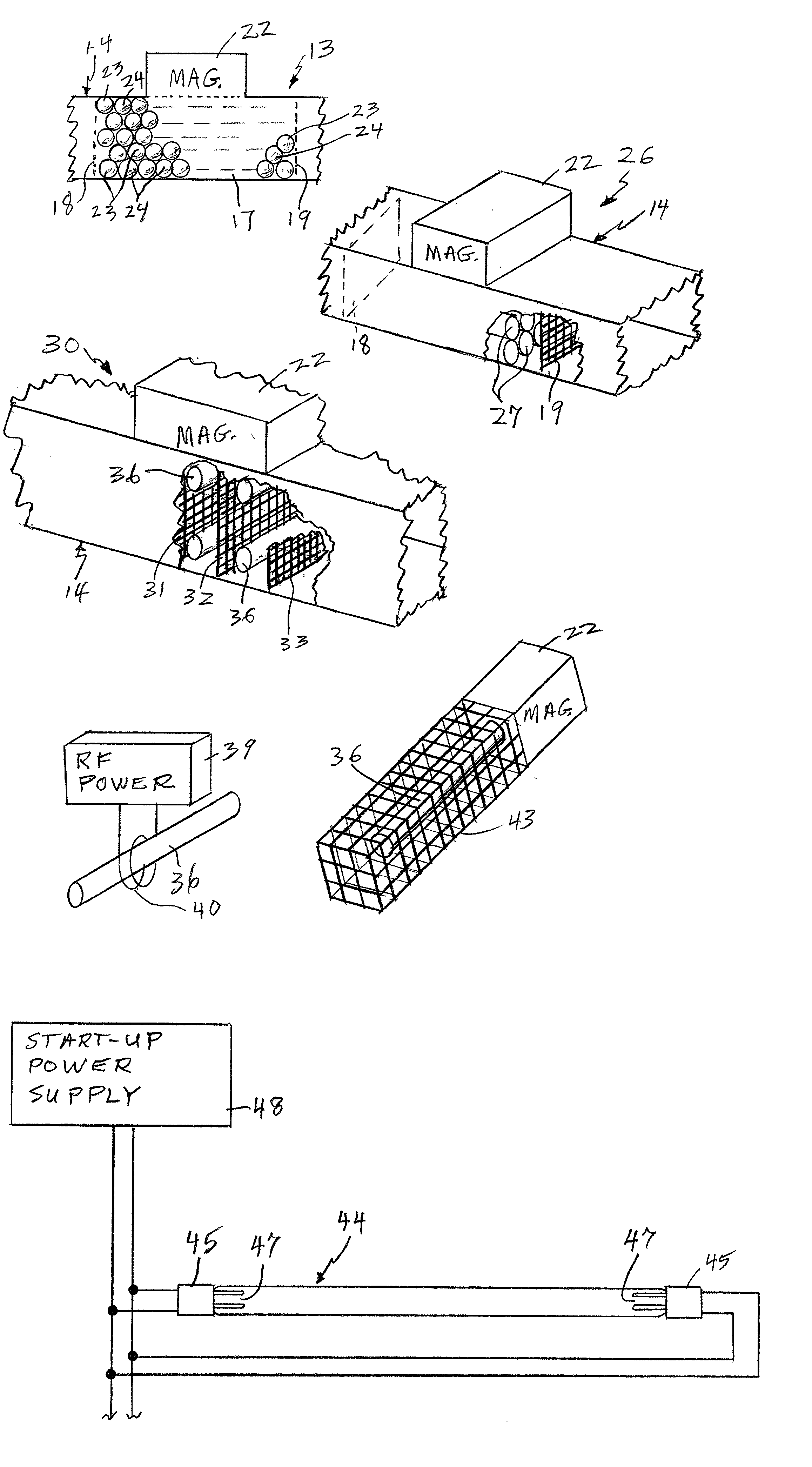
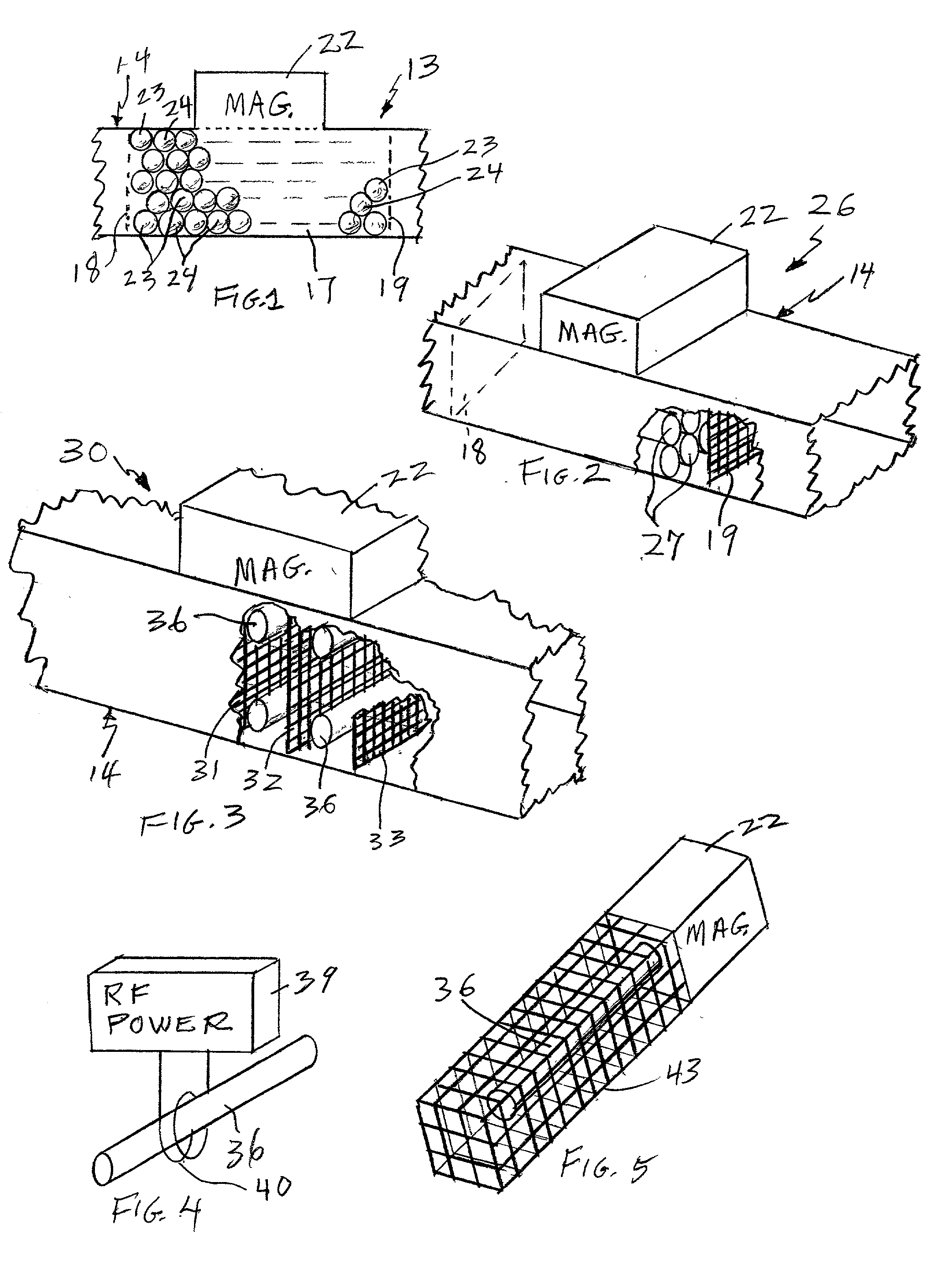
[0018] In FIG. 1, a fluid remediation zone 13 is formed within a duct 14 which comprises microwave reflecting material. At each end of a finite space 17, microwave reflectors 18, 19, which are permeable to the fluid in the duct 14, form a resonant microwave cavity. A magnetron 22 provides microwave electromagnetic radiation into the cavity. Within the cavity are spheres 23, 24. The spheres 23, 24 may all comprise spherical electrodeless microwave lamps, in which case the fluid remediation zone of FIG. 1 operates to wholly or partially destroy microorganisms by means of ultraviolet radiation alone. On the other hand, in accordance with the invention, the spheres 23 may comprise spherical electrodeless ultraviolet lamps and the spheres 24 may be non-lamp spheres having an ultraviolet-activated photocatalyst surfaces, in which case the fluid remediation zone of FIG. 1 utilizes photocatalyst reaction with the fluid to remediate the fluid in some fashion, such as to oxidize or reduce org...


PUM

PropertyMeasurementUnit
Poweraaaaaaaaaa
Flow rateaaaaaaaaaa
Permeabilityaaaaaaaaaa

Abstract

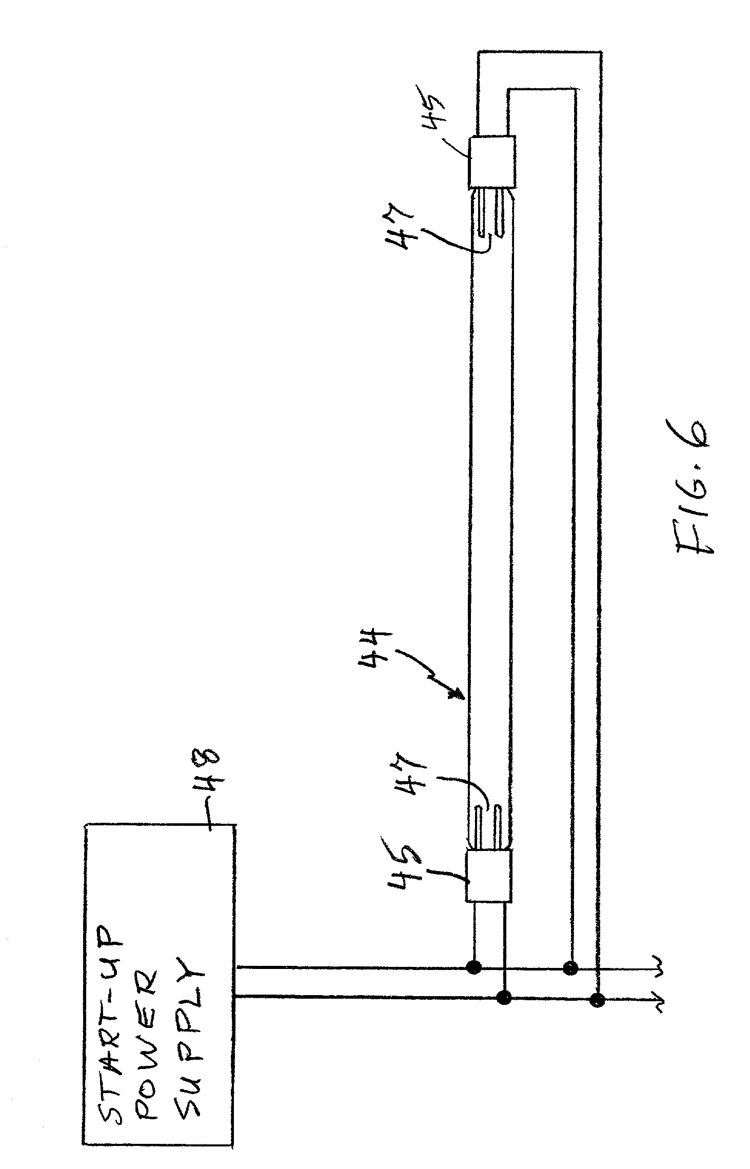
Spherical (23) or cylindrical (27, 36) electrodeless ultraviolet lamps are used to remediate fluid, directly or by excitation of ultraviolet-activated photocatalyst surfaces, which may be on the lamps themselves, or on structures which are permeable by the fluid. The lamps may be excited in cavities (18, 19; 43) by microwave energy from a magnetron (22), or by radio frequency power (39) inductively coupled (40) to the lamps. The lamps (44) may have start-up electrodes (47).

Description

[0001] This invention relates to remediation of fluids in a finite space by means of ultraviolet radiation from electrodeless ultraviolet discharge devices, including the excitation of photocatalytic surfaces to promote chemical reactions.[0002] Typical air purifiers use electrode discharge ultraviolet lamps; in some cases, the ultraviolet light is relied upon to wholly or partially destroy microorganisms; in other cases, the ultraviolet light activates a photocatalyst on the surface of a packed bed of pellets or of a structure which is permeable by the air flowing therethrough. Similar apparatus may be used in chemical processes in which photocatalytic oxidation of air or water streams is performed either to remediate (i.e., sterilize) or otherwise condition the stream.[0003] Because of the short lamp life, air-purifier designs must be made suitable for lamp changeover. Such designs are unnecessarily large in volume, require a large number of ultraviolet lamps and photocatalyst ele...

Claims


Application Information

Patent Timeline
IPC IPC(8): A61L9/20A61L9/00B01D53/00B01D53/86B01J19/12B01J35/02C02F1/30C02F1/32C02F1/72H01J65/04
CPCA61L9/20A61L9/205B01D53/007B01D2259/804C02F1/325H01J65/042C02F2201/32C02F2201/326C02F2305/10H01J61/92C02F1/725
Inventor OBEE, TIMOTHY N.HAY, STEPHEN O.SANGIOVANNI, JOSEPH J.HERTZBERG, JARED B.
Owner CARRIER CORP
Why Eureka
Try Eureka