Electro-optical transceiver system with controlled lateral leakage and method of making it

a transceiver and optical technology, applied in the direction of lasers, semiconductor laser structural details, semiconductor lasers, etc., can solve the problems of data transfer into and out of processors, light leakage laterally, and noise in the received signal

Inactive Publication Date: 2003-11-20
ALTERA CORP
View PDF11 Cites 17 Cited by
  • Summary
  • Abstract
  • Description
  • Claims
  • Application Information

AI Technical Summary

Benefits of technology

[0006] It is a further object of this invention to provide such an improved electro-optical transceiver system and method which blocks lateral leakage of light from emitters to detectors.
[0008] It is a further object of this invention to provide such an improved electro-optical transceiver system and method that beneficially directly applies the laterally leaked light without electronic circuitry to enhance system performance.
[0009] It is a further object of this invention to provide such an improved electro-optical transceiver system and method which reduces cross-talk in the plane of the array of the transceivers.
[0010] It is a further object of this invention to provide such an improved electro-optical transceiver system and method which improves the signal to noise ratio.
[0011] It is a further object of this invention to provide such an improved electro-optical transceiver system and method which effects control of the lateral light leakage as an integrated part of the integrated circuit fabrication process and with minimal additional steps.
[0024] The invention also features a method for integration of low lateral light leakage photonic devices on an integrated circuit including flip chip bump bonding a first chip having first photonic devices to a second chip having second photonic devices and filling the voids between the chips interstitially of the devices with an underfill at least a portion of which blocks light at the wavelength at which the photonic devices operate.

Problems solved by technology

However, data transfer into and out of processors remains a limiting factor.
However, some light leaks laterally, and it can be detected by a nearby detector.
This light adds noise to the signal received at that detector, which detracts from the overall performance of the system.
In many devices, there is a need to make separate circuitry that uses that signal / information to enhance system performance, but such circuitry adds cost to the structure.
Light leaking from an emitter to neighboring detectors constitutes a loss of optical power, which can adversely affect the performance of some systems, especially where the coupling is weak.

Method used


Image

  • Electro-optical transceiver system with controlled lateral leakage and method of making it
  • Electro-optical transceiver system with controlled lateral leakage and method of making it
  • Electro-optical transceiver system with controlled lateral leakage and method of making it

Examples


Embodiment Construction

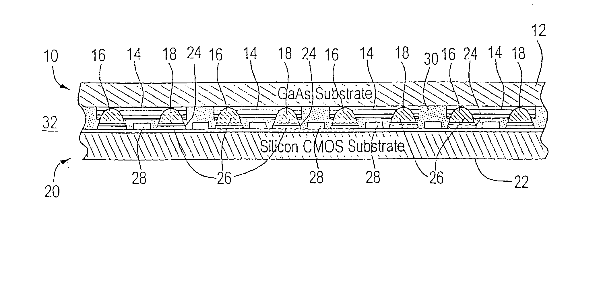
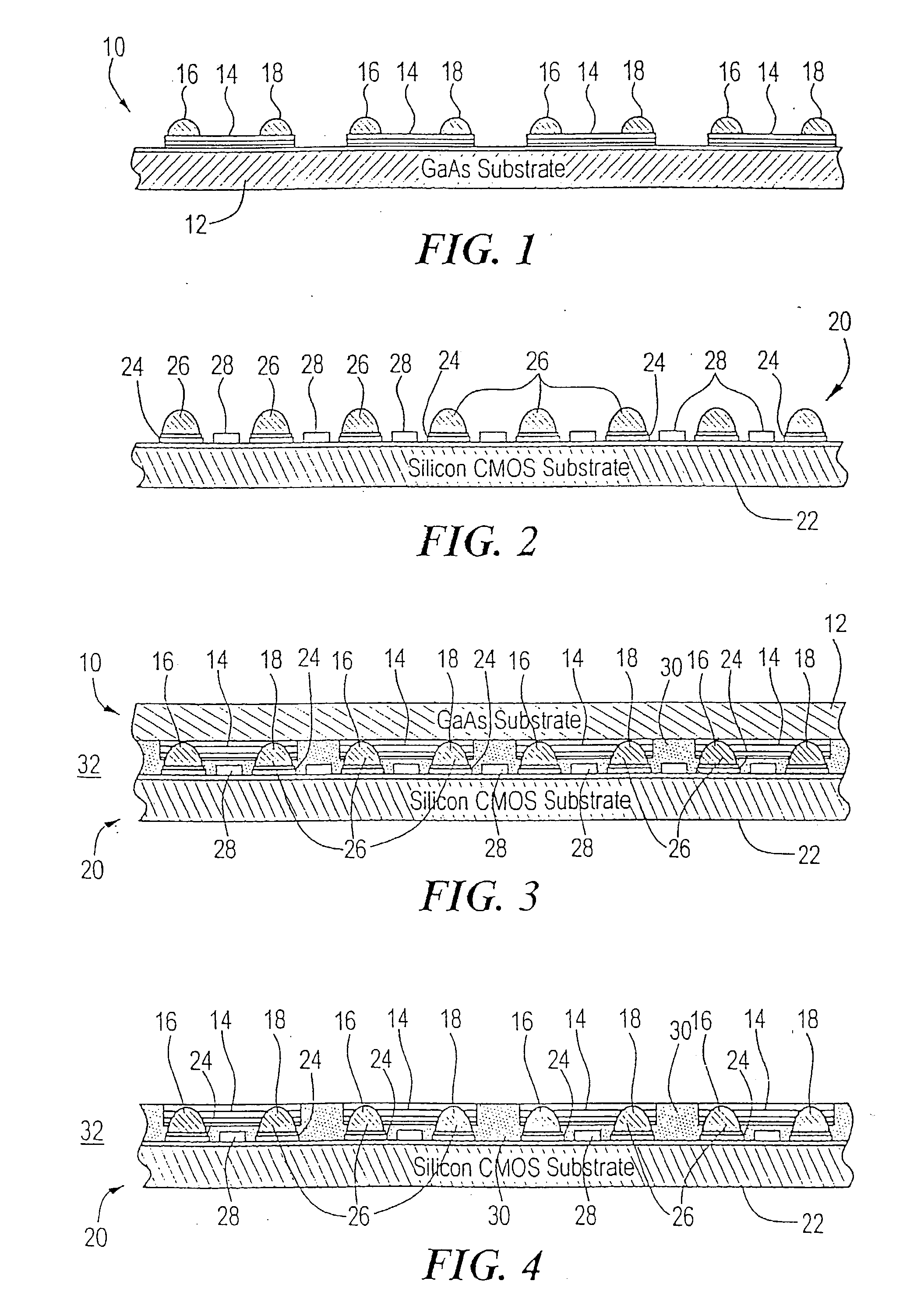
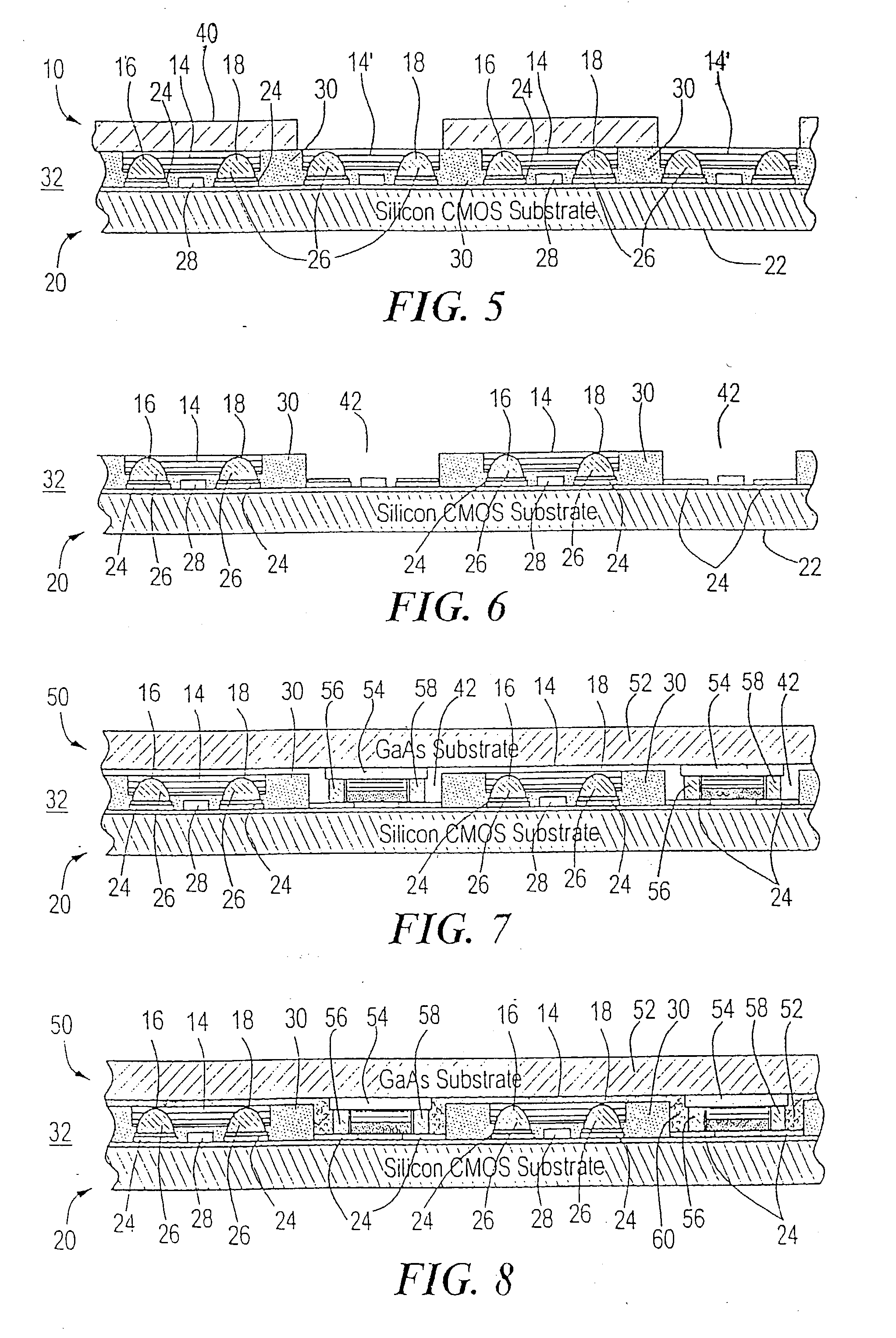
[0042] There is shown in FIG. 1 a first chip 10 including a GaAs substrate 12 having grown on it a number of vertical cavity surface emitting laser (VCSEL) emitters 14. Mounted on each of the VCSELs 14 are a number of solder balls or bumps two of which are shown 16 and 18. Some of these devices 14 are actually dummy devices and will be removed as seen subsequently with respect to FIGS. 5 and 6.

[0043] The second chip 20, FIG. 2, includes a silicon CMOS substrate 22 which carries a number of metal landing pads 24 each containing a solder ball or bump 26 so arranged that they mate with the solder bumps 16 and 18 of chip 10, FIG. 1. Also shown on chip 20 are portions 28 of an electronic circuit in this case an application specific integrated circuit (ASIC).

[0044] The first chip 10, FIG. 1 is flip-chipped and bump bonded onto the second chip 20 as shown in FIG. 3 and filled with an underfill 30 such as an epoxy, a photoresist, or any other suitable flowable hardener. Underfill 30, FIG. 3...


PUM


Abstract

An electro-optical transceiver system with controlled lateral light leakage and a method of making such a system includes a plurality of emitter devices and detector devices including at least one of each, arranged in a planar array for transmitting and receiving, respectively, energy in a predetermined wavelength and a blocking medium disposed interstitially of the devices and being absorbing at the predetermined wavelength for blocking energy at the predetermined wavelength laterally leaking from an emitter device to one or more detector devices.

Description

[0001] This is a divisional application which claims priority under 35 U.S.C. .sctn.120 to co-pending patent application Ser. No. 10 / 241,991, filed Sep. 12, 2002, which is incorporated herein by reference for all purposes and which in turn is a divisional application which claims priority under 35 U.S.C. .sctn.120 to then co-pending patent application Ser. No. 10 / 016,382 filed Dec. 10, 2001, now issued U.S. Pat. No. 6,485,995, which is incorporated herein by reference for all purposes and which in turn is a divisional application which claims priority under 35 U.S.C. .sctn.120 to then co-pending patent application Ser. No. 09 / 653,378 filed Sep. 01, 2000, now issued U.S. Pat. No. 6,344,664, which is incorporated herein by reference for all purposes, which in turn claims priority under 35 U.S.C. .sctn.119 to U.S. Provisional Patent Application No. 60 / 168,491, filed Dec. 02, 1999, which is incorporated herein by reference for all purposes.[0002] This invention relates to an electro-opt...

Claims


Application Information

Patent Timeline
Patent Type & Authority Applications(United States)
IPC IPC(8): H01L25/075H01S5/02H01S5/026H01S5/183
CPCH01L25/0753H01S5/021H01S5/0217H01S5/423H01S5/0262H01S5/0264H01S5/183H01S5/02272H01L2924/0002H01S5/0237H01L2924/00
Inventor TREZZA, JOHN A.DUDOFF, GREGORY K.
Owner ALTERA CORP
Why Eureka
Try Eureka