Integrated scanning and ocular tomography system and method

a technology of ocular tomography and integrated scanning, applied in the field of integrated scanning and ocular tomography system and method, can solve the problems of difficult sampling of corneal thickness over tissue area, length of time required to measure corneal thickness, and inability to measure a single point or small central region, etc., to achieve simple and efficient monitoring and measurement of corneal thickness

Inactive Publication Date: 2004-02-05
AMO MFG USA INC
View PDF33 Cites 96 Cited by
  • Summary
  • Abstract
  • Description
  • Claims
  • Application Information

AI Technical Summary

Benefits of technology

0008] The present invention is generally directed to systems and methods measuring at least one reflecting surface of an object disposed along an optical path. A measured optical interference signal for each of at least three wavelengths of reflected light is used to determine a frequency component of a Fourier series. Frequency components of a Fourier series may be transformed to spatial components. Spatial components describe intensities and positions of light reflected along an optical path. Systems and methods of the present invention permit rapid measuring and monitoring of corneal thickness during surgery. Specific embodiments of the invention provide simple and efficient ways of measuring tomography of a cornea during ablation. The invention may do so by integrating an ablation device and a measurement apparatus into a single system.

Problems solved by technology

Problems encountered with techniques for measuring a tomography of a cornea have often included a length of time required to measure corneal thickness and difficulty sampling corneal thickness over an area of tissue, as opposed to sampling thickness at a single point of tissue.
Measuring a single point or small central region is less than ideal because such measurements typically represent only a small portion of a total treated area.

Method used


Image

  • Integrated scanning and ocular tomography system and method
  • Integrated scanning and ocular tomography system and method
  • Integrated scanning and ocular tomography system and method

Examples


Embodiment Construction

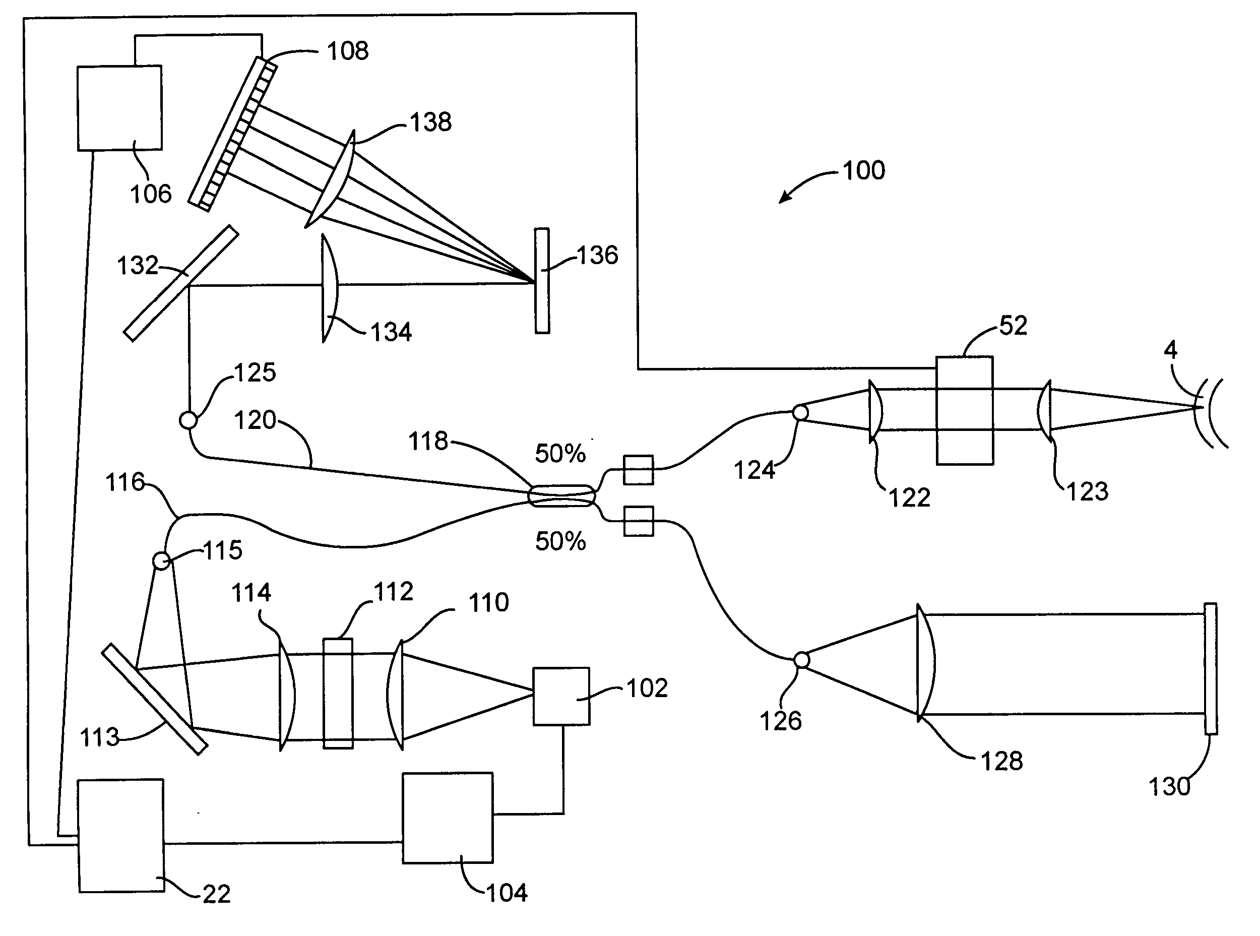
[0035] The present invention is particularly useful for enhancing accuracy and efficacy of laser eye surgical procedures, such as photorefractive keratectomy (PRK), phototherapeutic keratectomy (PTK), laser assisted in situ keratomileusis (LASIK), laser subepithelial keratomileusis (LASEK) and the like. Preferably, the present invention can provide enhanced optical accuracy of refractive procedures by improving a corneal ablation of a refractive treatment program. Hence, while the system and methods of the present invention are described primarily in a context of a laser eye surgery system, it should be understood techniques of the present invention may be adapted for use in alternative eye treatment procedures and systems such as spectacle lenses, intraocular lenses, contact lenses, corneal ring implants, collagenous corneal tissue thermal remodeling, and the like.

[0036] Systems and methods of the present invention permit rapid measurements of an object having reflecting and scatte...


PUM


Abstract

Systems and methods of the present invention measure at least one reflecting surface of an object disposed along an optical path. In some embodiments a measured optical interference signal for each of at least three wavelengths of reflected light may be used to determine a modulation of frequency components of a Fourier series. Frequency components of a Fourier series may be transformed to spatial components that describe intensities and positions of light reflected along an optical path. Systems and methods of the present invention permit rapid measuring and may monitor corneal thickness during surgery. The invention may do so by integrating an ablation device and a measurement apparatus into a single system. An integrated scanning and monitoring system may include an ablative light source producing an ablative beam and a measurement light source producing a measurement beam.

Description

[0001] This is a regular patent application which claims priority under 37 C.F.R. 1.78(a) from U.S. Provisional Patent Application No. 60 / 392,330 filed Jul. 27, 2002, the full disclosure of which is incorporated herein by reference.[0002] The present invention relates generally to measurements of tissues, optical elements and other structures, and, more particularly, to methods and systems for integrated ocular tomography and scanning laser ablation.[0003] Corneal shape corrective surgeries are commonly used to treat myopia, hyperopia, astigmatism, and the like. Procedures employing an excimer laser include LASIK (Laser Assisted In-Situ Keratomileusis), PRK (Photo Refractive Keratectomy) and LASEK (Laser Subepithelial Keratomileusis). During LASIK, a suction ring is typically placed over sclera tissue (the white part of the eye) to hold the eye firmly. A surgeon first uses a microkeratome with an oscillating steel blade to make a partial cut through a front surface of a cornea. A mi...

Claims


Application Information

Patent Timeline
Patent Type & Authority Applications(United States)
IPC IPC(8): A61B3/10A61B19/00A61F9/01G01B9/02
CPCA61B3/1005G01B2290/25A61F9/008A61F9/00804A61F9/00812A61F2009/00842A61F2009/00851A61F2009/00853A61F2009/00872A61F2009/0088A61F2009/00882A61F2009/00897G01B9/02007G01B9/02044G01B9/02002G01B9/0209G01B9/02091G01B2290/70A61B2019/461A61B2090/061
Inventor SHIMMICK, JOHN K.
Owner AMO MFG USA INC
Why Eureka
Try Eureka