

Motor using magnet
a technology of magnets and motors, applied in the direction of magnetic circuit rotating parts, magnetic circuit shapes/forms/construction, magnetic bodies, etc., can solve the problems of low temperature characteristics and residual magnetic flux density of hard magnetic materials disclosed in physical review b, and insufficien
- Summary
- Abstract
- Description
- Claims
- Application Information
AI Technical Summary
Benefits of technology
Problems solved by technology
Method used
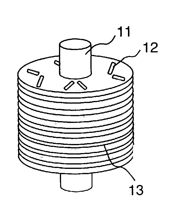
Image

Examples
example 2
[0044] The second Example will be explained. As rare earth elements, Nd and Dy were selected to prepare a raw material composition consisting of (Nd,Dy).sub.2Fe.sub.14B. The raw material composition was melted and alloyed by an induction heating.
[0045] An additive amount of Dy was 0.5 to 1.0% by weight per Nd. Nd and Dy were added in an excess amount by about 5% by weight to compensate their loss at the time of heating.
[0046] Then, the alloy was crashed by a stamp mill or a jaw crasher to obtain a rough powder of 100 micrometers on average. Thereafter, the powder was ground by a jet mill to obtain fine powder of 3 to 5 micrometers on average. A ball mill can be used for the final grinding.
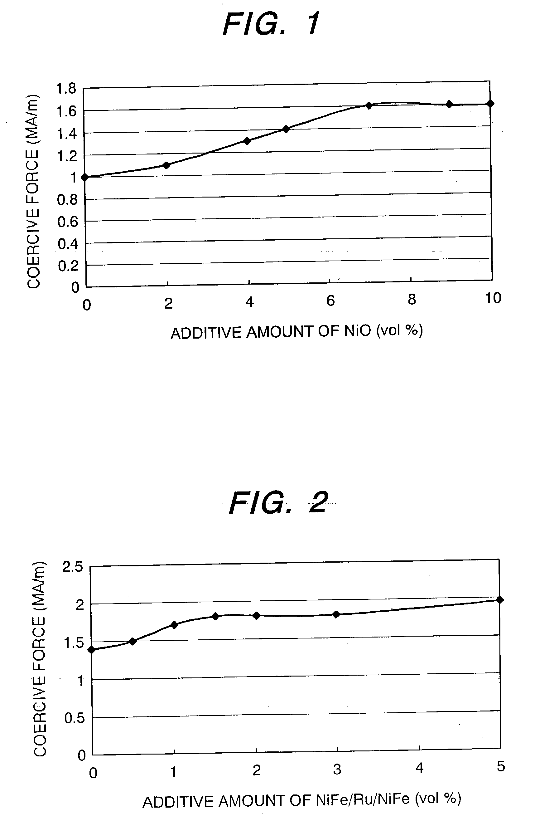
[0047] The fine powder was treated at 600 to 850.degree. C. in a hydrogen atmosphere to remove oxides on the surface of the grains. Then, the powder was mixed with the anti-ferromagnetic powder. The anti-ferromagnetic material was NiFe / Ru / NiFe.
[0048] A laminate was prepared by an atomizing method. ...
example 3
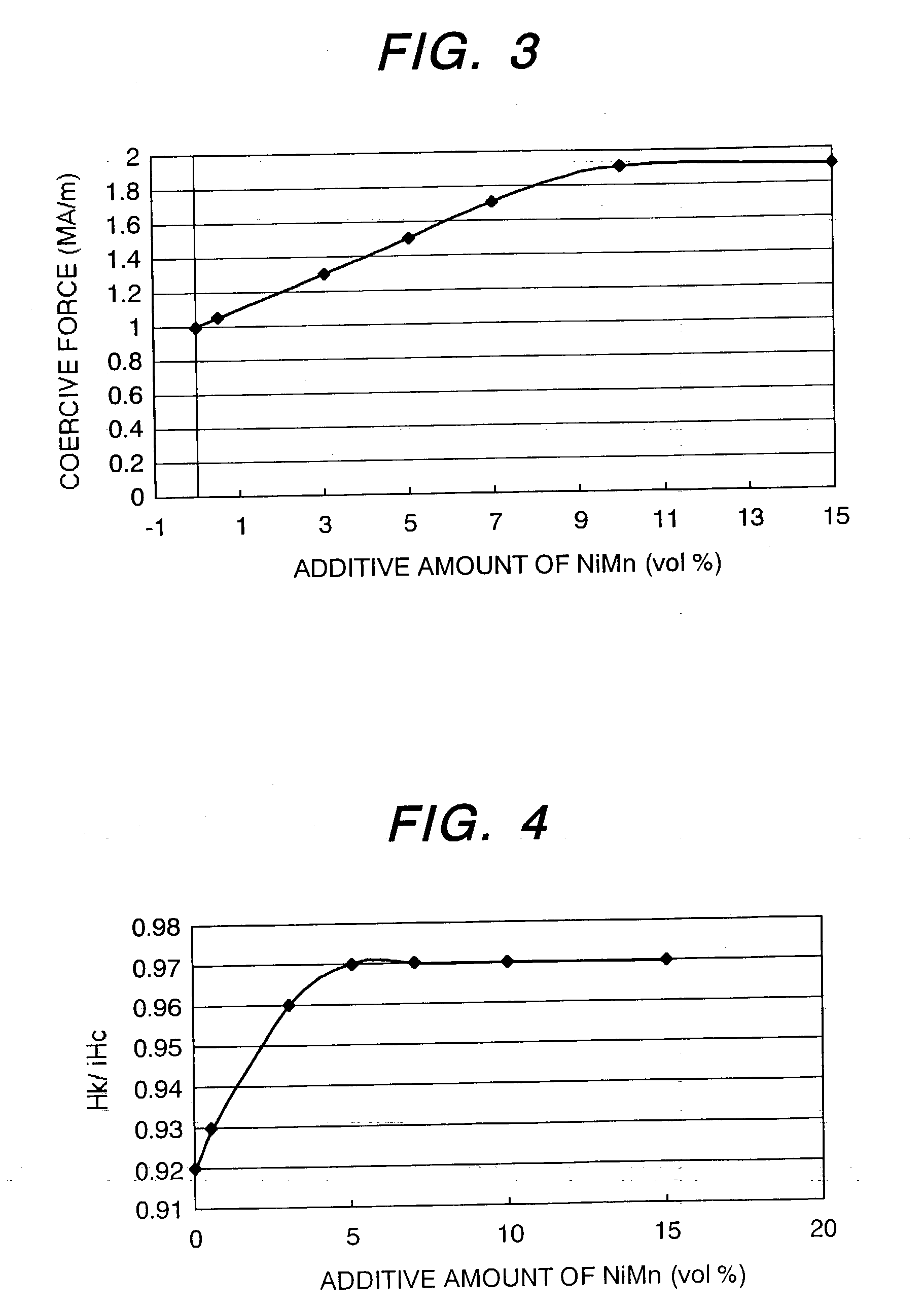
[0053] The next example will be explained. As the anti-ferromagnetic material, manganese alloys were chosen. Gas atomizing methods or liquid quenching methods were employed to prepare manganese alloy powder. The manganese alloys are exemplified as NiMn, FeMn, PdMn, IrMn and PtMn. In case of NiMn, a regular phase is formed, while in other cases, irregular phases are formed. The average particle size of the above manganese alloys was 1 to 5 micrometers. The smaller the particle size, the higher the coercive force can be obtained.
[0054] The case where NiMn is used will be explained below. A gas atomizing method for atomizing Ni--Mn alloy can produce a Ni--Mn alloy powder of Ni 50% by volume (.+-.1%)-Mn as being balance of an average particle size of 1 to 5 micrometers. The resulting powder was mixed with magnetic powder containing at least one rare earth element and having an average particle size of 5 to 100 micrometers.
[0055] A v-mixer or ball mill was used for mixing the powders in ...
example 4
[0073] In the following an example is described wherein IrMn, PdMn or FeMn that are all irregular phases were used as an anti-ferromagnetic material. There is shown in the following a method of making a hard magnetic material containing alloys Ir 10 to 30% by volume-Mn bal., Pd 10 to 30% by volume-Mn bal. or Fe 30 to 60 at %-Mn bal., or tertiary alloys each consisting of CrMnPt, IrMnPd, etc.
[0074] Hard magnetic materials are ones whose principal phase is compounds containing at least one rare earth element, Fe, Co, B, C and / or N. The materials were melted in vacuum (1.times.10.sup.-2Pa or less) to make a solid solution, followed by chemical analysis and crashing. Crashing was conducted in nitrogen or argon atmosphere. Further, the grains were subjected to grinding by means of a jet mill or a ball mill to obtain fine powder of a particle size of 1 to 5 m. The magnet was produced by vapor-depositing the anti-ferromagnetic material on the hard magnetic material. The hard magnetic mater...
PUM
| Property | Measurement | Unit |
|---|---|---|
| atomic numbers | aaaaa | aaaaa |
| particle size | aaaaa | aaaaa |
| grain size | aaaaa | aaaaa |
Abstract
Description
Claims
Application Information