
Chip quartz oscillator and liquid-phase sensor

Inactive Publication Date: 2004-03-18
OKAHATA YOSHIO +1
View PDF8 Cites 24 Cited by
  • Summary
  • Abstract
  • Description
  • Claims
  • Application Information

AI Technical Summary

Benefits of technology

[0019] In the present application of the invention, a new design is presented which attempts to overcome these problems that were unsolved by the prior art.
[0020] Thus an object of the present invention is to provide a chip quartz oscillator in which the quartz oscillator is prevented from being distorted by external deformation forces. This is achieved by a device according to claim 1, in which a quartz oscillator is flexibly fixed on a substrate by using an elastic bonding agent.
[0021] A further object of the present invention is to provide a combined quartz oscillator element, in which multiple chip quartz oscillators can be arranged on a common mounting substrate. This is achieved by a device having the features of claim 2.
[0022] Another object of the invention is to provide chip quartz oscillators in which the provision of a flexible mounting is provided by means which can easily accommodate variations in size of the quartz oscillators. This is achieved by means of a device having the features of claim 3.
[0023] A further object of the present invention is to provide chip quartz oscillators in which the quartz oscillator mounting forces are spread evenly over the circumference of the quartz oscillator. This is achieved by means of a device having the features of claim 4.
[0024] An additional object of the present invention is to provide chip quartz oscillators in which liquid is prevented from coming into contact with the non-detection electrode of the quartz oscillator. This is achieved by means of a device having the features of claim 5.
[0025] Another object of the present invention is to provide chip quartz oscillators in which the quartz oscillator is supported by a substrate without the oscillation of the quartz oscillator being affected by the substrate. This is achieved by means of a device having the features of claim 6.
[0026] An additional object of the present invention is to provide chip quartz oscillators in which the quartz oscillator oscillation is not degraded by the stiffness of the mounting mean. This is achieved by means of a device having the features of claim 7.
[0027] Yet a further object of the present invention is to provide a batch-type liquid-phase quartz oscillator sensor in which a steady oscillation is achieved and unaffected by the pressure fluctuation of the solution. This is achieved by a device having the features of claim 9, in which a chip quartz oscillator is installed on the inner wall of a tub-like vessel able to retain a sample solution.
[0028] Another object of the present invention is to provide a flow-type liquid-phase quartz oscillator sensor, in which an unfavourable pressure exerted by mounting is not applied to the fixed quartz oscillator and in which insulation is ensured between the electrodes of quartz oscillator; which sensor has a detection cell for liquid to be tested and works with only the detection electrode on the quartz oscillator surface immersed in a flowing liquid; and in which steady oscillation is achieved and unaffected by the pressure fluctuation of the solution caused by flow rate fluctuation. This is achieved by a device having the features of claim 10.
[0029] Yet another object of the present invention is to provide a quartz oscillator device, with means for preventing the fluctuation of oscillation frequency resulted from the variation of power source voltage caused by external noises and achieving a steady oscillation; and which helps to improve the effective sensitivity of a liquid-phase sensor. This is achieved in accordance with the present invention by a device in accordance with claim 8, in which the output from the oscillation circuit section including the chip quartz oscillator with a reduced Q due to immersing the detection electrode in a liquid is transmitted through a photocoupler section to an external device and electrical power is supplied by a battery; in which the whole circuit is shielded to insulate the electrical component for detection consisting of the oscillation circuit section, photocoupler section and power source section from external electrical components.
[0030] A further object of the present invention is to provide a method for making quartz oscillator devices in accordance with the present invention. Such a method is in accordance with claim 11.

Problems solved by technology

However, a problem occurs when the quartz oscillator, which is an electrical element originally designed on the assumption of using it in a gaseous phase, is used as a sensor in a conducting solution--namely an electrical short-circuit occurs between the electrodes in solution.
In addition, in the liquid-phase sensor, in which the quartz plate is exposed to a liquid with a high viscosity as compared with gas, being in contact with liquid itself may have an interfering effect and, as a consequence, the Q may decrease greatly; the Q may also decrease to the minimum due to an improper mechanical construction.
However, the adjustment of the tightening pressure for the O-ring or gasket 49 is so delicate that reproducibility is unable to be expected.
Furthermore, the quartz plate itself is handled directly when it is being placed between the O-rings or gaskets 49 in a narrow flowcell, and therefore, there is a risk of damaging the fragile quartz plate.
Even when fixed firmly, the quartz oscillator might be distorted due to pressure fluctuations in the solution being tested.
Moreover, in the case of the infinitesimal deformations of the vessel caused by temperature changes or hydraulic pressure changes, the quartz plate is directly stressed by such deformations.
In any event, such deformations of the quartz oscillator resulted in a marked decrease in the Q and an unsteady oscillation in the liquid-phase sensor; many examples have shown that the oscillation halts in the worst case.
However, a relatively large amount of sample solution is required for the measurement, even when it is possible to immerse such a bulky structure (i.e. the quartz oscillator with the covering) in the sample solution.
This, as a matter of course, limits the range of objects testable by the liquid-phase sensor; it is unsuitable for measurements in which only a small amount of sample is available for the detection of substances including the above-mentioned bio-functional molecules.
However, it is difficult to install the quartz oscillator with the components as disclosed in the above-mentioned patent into a flow cell, and even if it were possible, further efforts are required to design the device in which a quartz oscillator itself is not subjected to deformation forces from the fixation vessel.
This means impairment of the frequency maintenance ability or the high buffer action, which is an original property of the quartz oscillator, against the change of electrical load of applied voltage, etc. or against the change of mechanical load resulted from the change in the physical properties (pressure, viscosity, etc.) of solution in contact with the device.
As compared with the quartz oscillator placed in a gas phase, a sensor operating in a liquid phase displays a lot of noise and / or large drifts, because its output signal changes easily according to the load fluctuations as described above.
Thus, when usual quartz oscillator circuits, which had been developed on the assumption that the oscillation occurs in a gas phase, were used in liquid-phase sensors without any modification, steady oscillation was often impossible to achieve.
These publicly known technologies can be assumed as an effective strategy when the energy is dissipated markedly, and thus, the quartz oscillator halts, but the Q of quartz oscillator is not improved based on the strategy.
Because of this, it is ineffective for noises from the concomitant devices, for example, noise directly transmitted from the DC power source unit for rectification and voltage drop down of the power from the AC line or transmitted from output-signal processing systems as well as fluctuations of applied power voltage due to radiation noise around the quartz oscillator.
Thus, improvement of the effective sensitivity cannot be achieved by these methods.
In addition, device multiplexing, specifically, the arrangement of multiple oscillation circuits in a single device unit has not been assumed in the above-mentioned disclosed technologies.
However, this example is not designed for device multiplexing, and the signals from a pair of differentially operating quartz oscillator sensors, of which one is for sample measurement and the other is for reference measurement, are connected directly inside the closed circuit.
Thus, there is the problem of short-circuits between the oscillation circuits that occur as the pair of quartz oscillator sensors is immersed into the same solution.
In this example of circuit, the insulation is achieved by using the transformer, and therefore, it has a small effect on the noises from external signal processing system or the influences of load fluctuation, but it cannot remove the elements of alternating noise such as high frequency noise, etc.

Method used


Image

  • Chip quartz oscillator and liquid-phase sensor
  • Chip quartz oscillator and liquid-phase sensor
  • Chip quartz oscillator and liquid-phase sensor

Examples


first embodiment

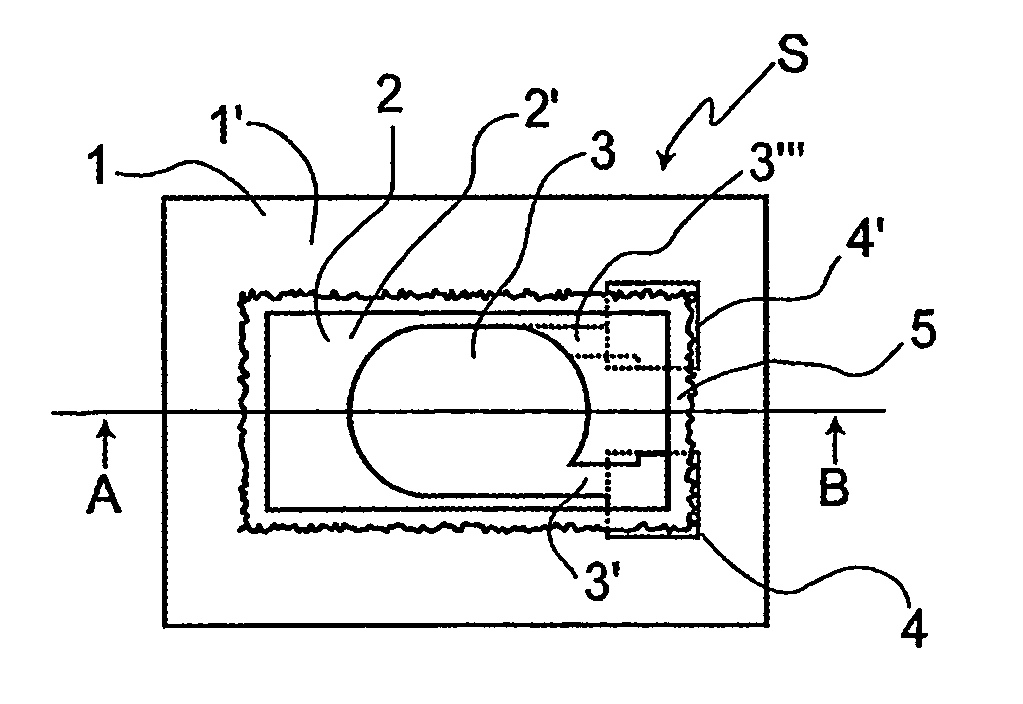
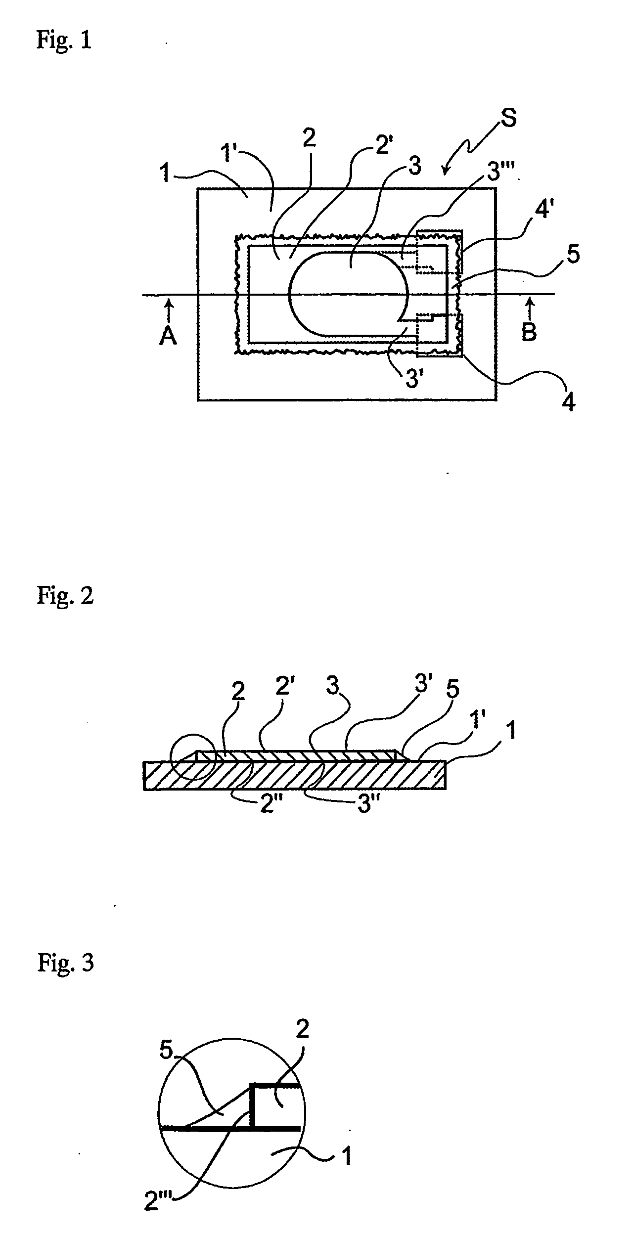
[0050] FIG. 1 is a plan view from above schematically showing the chip quartz oscillator of the present invention, and FIG. 2 is a sectional view along the line A-B indicated in FIG. 1. In these figures, the chip quartz oscillator S has a rectangular quartz oscillator 2 placed on the upper surface 1' of a substrate 1. Substrate 1 is made of any material which is rigid, non-conducting or able to retain a non-conducting coating, non-soluble in the liquids being tested and preferably inexpensive and easy to work with. Many engineering plastics, metals and ceramics are suitable for this use, in particular the types used for making circuit boards. The quartz oscillator 2 has a detection electrode 3 on a first surface 2' and a non-detection electrode 3" on the opposite second surface 2" i.e. in this case the side facing towards the upper surface 1' of the substrate 1. In an example of an embodiment of the present invention the quartz oscillator 2 is in the order of 4 mm long, 1.6 mm wide ...

second embodiment

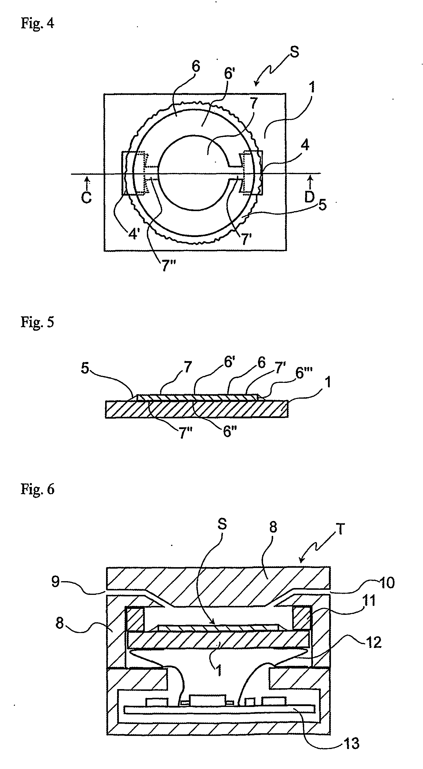
[0067] Several application examples will be described here in regard to the chip quartz oscillator S of the present invention. FIG. 6 is a sectional view showing an example of a flow-type liquid-phase quartz oscillator sensor using a chip quartz oscillator S of the first or second embodiment described by referring to FIGS. 1-5. An inflow entrance 9 and a drain hole 10 are arranged in the vessel 8, to enable a sample solution to enter the vessel and come into contact with the detection electrode of the chip quartz oscillator S inside-the flow-type liquid-phase quartz oscillator sensor T. The substrate of the chip quartz oscillator S is fixed between cushioning material 11, such as an elastic body such as an O-ring or a flexible gasket, and a preferably elastic electric junction 12, such as an elastic metal such as flat spring or dampening pin. The cushioning material 11 is used to preventing the sample solution from flowing into the region around the rear side of the substrate of the...


PUM


Abstract

The present invention relates to a chip quartz oscillator. In an embodiment of a chip quartz oscillator S in accordance with the present invention, a quartz oscillator 2, which has a detection electrode 3 on a surface thereof and a non-detection electrode on the other surface thereof, is fixed on a substrate 1, and each of the electrodes is connected electrically to a terminal 4 or 4' on the substrate 1. While keeping the non-detection electrode in contact with the substrate 1, the quartz oscillator 2 is fixed on the substrate 1, by flexibly bonding the side-wall 2''' of the quartz oscillator 2 along its circumference to the surface of the substrate 1 by using the elastic bonding agent 5. Thus, the oscillation surface of the quartz oscillator 2 is supported distributively on the substrate 1 in a surface-contacting and non-adhesive manner.

Description

TECHNICAL FIELD OF INDUSTRIAL APPLICATION[0001] The present invention relates to a quartz oscillator sensor and an oscillation circuit for a liquid-phase sensor in which an elastic wave element such as quartz oscillator is used as a detector immersed in a liquid medium.PRIOR ART[0002] Piezoelectric acoustic wave devices such as quartz oscillator can be utilised as mass sensors on the basis of the principle that a material adsorbed on the electrode surface changes the fundamental oscillation frequency of the oscillator in proportion to the mass of the adsorbate; the change has been proven experimentally to conform to the theoretical formula proposed by Sauerbrey (Sauerbrey, G., Z. phys. 155 (1959), p.206-222). Owing to the high detection sensitivity predicted by the formula, a micro-measurement method using such a sensor is far superior to general mass measurement methods using mechanical balances, and thus the method has been put into practical use, for example, in quantitative meas...

Claims


Application Information

Patent Timeline
IPC IPC(8): H03B5/32G01F23/22H03B5/36H03H9/02H03H9/05H03H9/10H03H9/19H03H9/215
CPCG01N29/036G01N2291/0256H03H9/19H03B5/36H03H9/0547H03B5/32
Inventor YOSHIMINE, HIROSHISOTA, HIROYUKI
Owner OKAHATA YOSHIO
Learn More