Converter and a method for the control thereof

a converter and control method technology, applied in the direction of dc-ac conversion without reversal, process and machine control, instruments, etc., can solve the problems of slow commutation and restrict the maximum modulation degree, and achieve the maximum modulation or control degree of the converter, improve the curve shape, and reduce the loss of voltage time area during the two commutation processes.

Inactive Publication Date: 2004-03-25
ABB (SCHWEIZ) AG
View PDF6 Cites 7 Cited by
  • Summary
  • Abstract
  • Description
  • Claims
  • Application Information

AI Technical Summary

Benefits of technology

[0011] The object of the present invention is to provide a converter and a method of the type defined in the introduction, which enable an increase of the maximum modulation degree of such a converter at phase currents exceeding a predetermined value.
[0013] By interlacing two subsequent commutation processes so that a second commutation process is started before the first commutation process has been completed, the voltage time area lost during the two commutation processes may be reduced considerably. This means that the maximum modulation or control degree of the converter may be increased and in the practice more power is delivered on the alternating voltage side of the converter. It will also be possible to obtain a better curve shape on the alternating voltage side and thereby reduce the problems of harmonics.

Problems solved by technology

These slow commutations constitute a drawback, since they restrict the maximum modulation degree of the converter.

Method used


Image

  • Converter and a method for the control thereof
  • Converter and a method for the control thereof
  • Converter and a method for the control thereof

Examples


Embodiment Construction

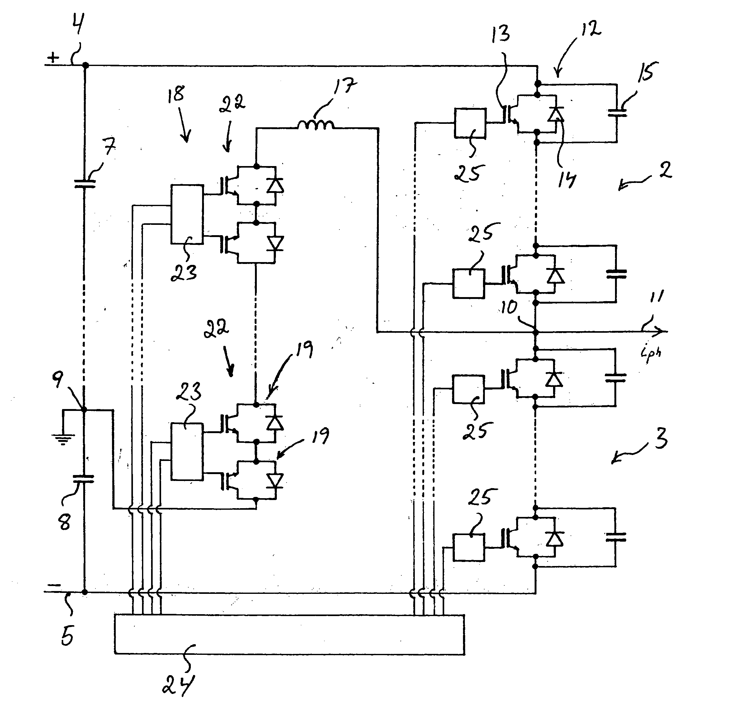
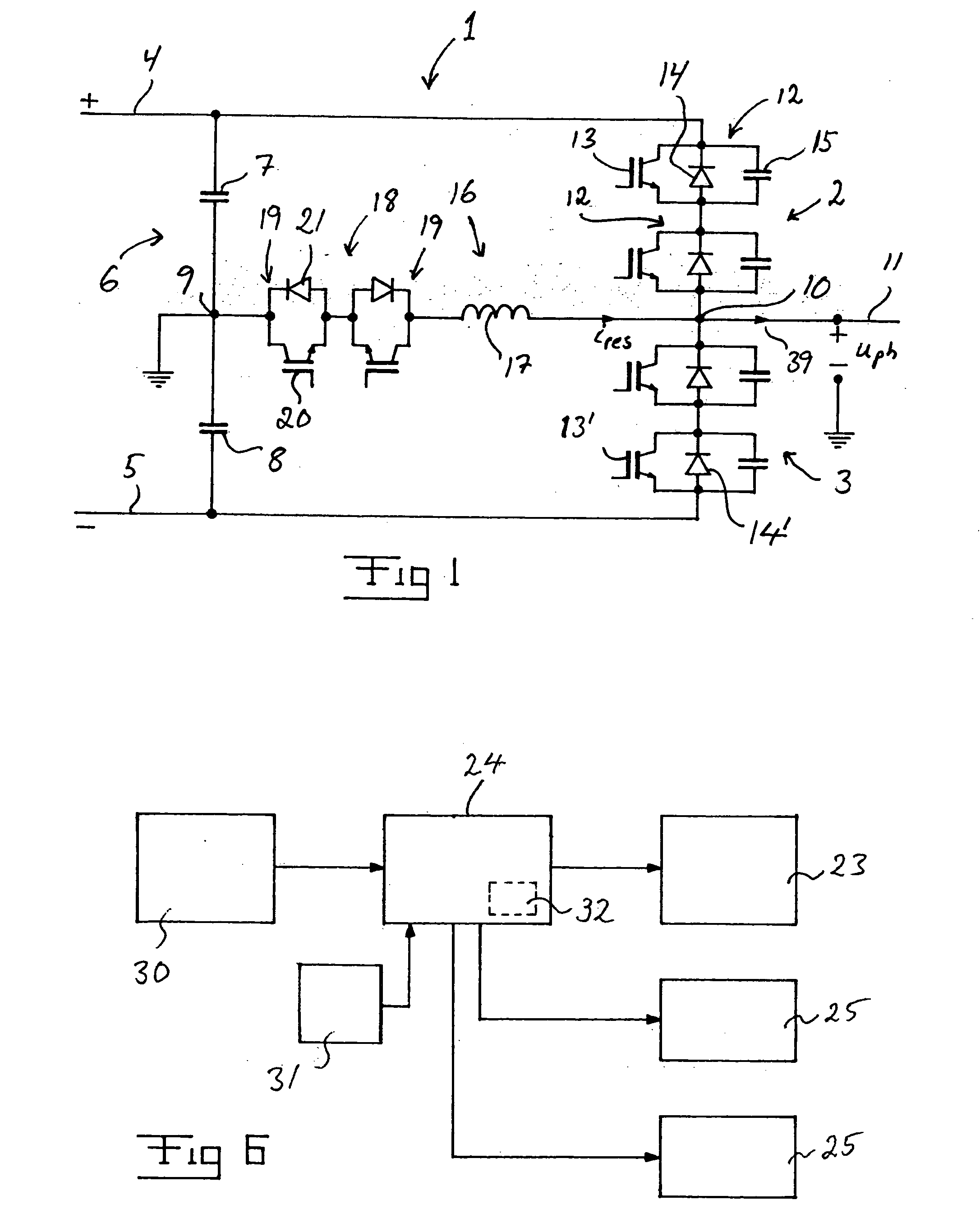
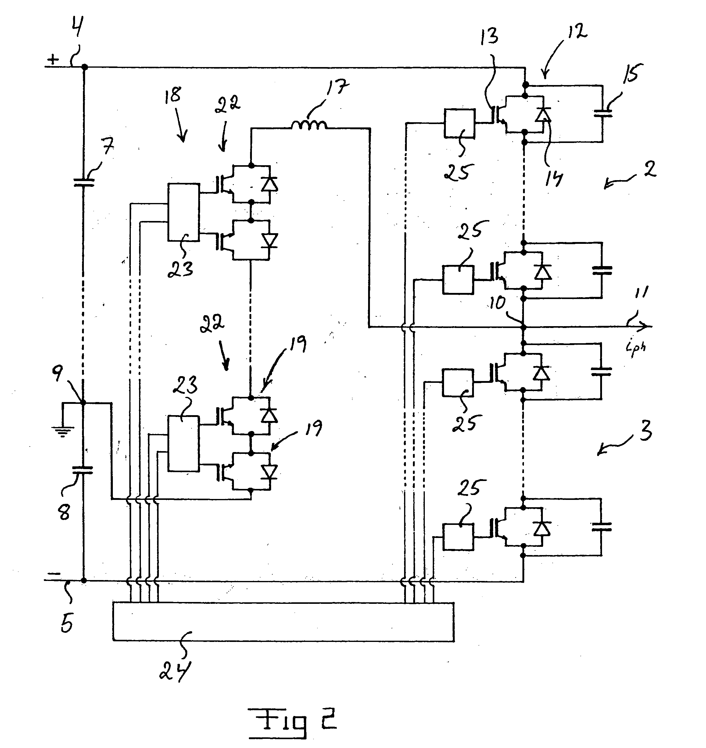
[0025] A converter according to an embodiment of the invention is illustrated in FIG. 1. The converter is a so-called VSC-converter. Only the part of the converter connected to one phase of an alternating voltage phase line is shown in FIG. 1, in which the number of phases is normally three, but it is also possible that this constitutes the entire converter when this is connected to a one phase alternating voltage network. The part shown of the converter constitutes a so called phase leg and a converter adapted for for example a three phase alternating voltage network comprises three phase legs of the type shown.

[0026] VSC-converters are known in various embodiments. A VSC-converter comprises in all embodiments a number of so called current valves, hereinafter called main valves, which each comprises a controllable semiconductor device, such as an IGBT (Insulated Gate Bipolar Transistor) or a GTO (Gate Turn-Off Thyristor), and a rectifying member in the form of a diode, a so called ...


PUM


Abstract

A converter has a resonance circuit with an auxiliary valve (18), an inductor (17) and capacitive members (15) for assisting the commutation of the converter. A control arrangement (24) is adapted to control turning-on and turning-off of controllable semiconductor devices of the main valve of the converter and controllable semiconductor components of the auxiliary valve. Means are arranged for measuring the current in the phase output (10) of the converter. When carrying out two subsequent commutation processes for changing the phase potential on the phase output from the potential of a first of the poles of a direct voltage side of the converter to that of a second of the poles and then back to the one of the first pole the second commutation process is started before the first one has been completed.

Description

FIELD OF THE INVENTION AND PRIOR ART[0001] The present invention relates to a converter according to the preamble of claim 1 and a method for control of such a converter.[0002] The invention relates especially to a VSC-converter. A VSC-converter for connection between a direct voltage network and an alternating voltage network is already known through for example the thesis "PWM and control of two and three level High Power Voltage Source Converters" by Anders Lindberg, Kungliga Tekniska Hogskolan, Stockholm, 1995, in which publication a plant for transmission of electric power through a direct voltage network for high voltage direct current (HVDC) while utilizing such converters is described. Known are also plants for transmitting electric power between a direct voltage network and an alternating voltage network based on line-commutated CSC (Current Source Converters)--converters used in stations for power transmission. However, another way to proceed is described in this thesis, w...

Claims


Application Information

Patent Timeline
Patent Type & Authority Applications(United States)
IPC IPC(8): H02M7/48H02M7/487
CPCH02M7/487H02M7/4826H02M7/4811
Inventor NORRGA, STAFFANBIJLENGA, BO
Owner ABB (SCHWEIZ) AG
Why Eureka
Try Eureka