Optical recording medium

a recording medium and optical recording technology, applied in the field of rewritable optical recording medium, can solve the problems of reduced crystallization temperature in the recording layer, amorphous marks are prone to crystallization, and the shape of amorphous marks is not uniform, so as to achieve excellent high-recording characteristics, large width, and large modulation degree

Inactive Publication Date: 2011-09-13
RICOH KK
View PDF21 Cites 2 Cited by
  • Summary
  • Abstract
  • Description
  • Claims
  • Application Information

AI Technical Summary

Benefits of technology

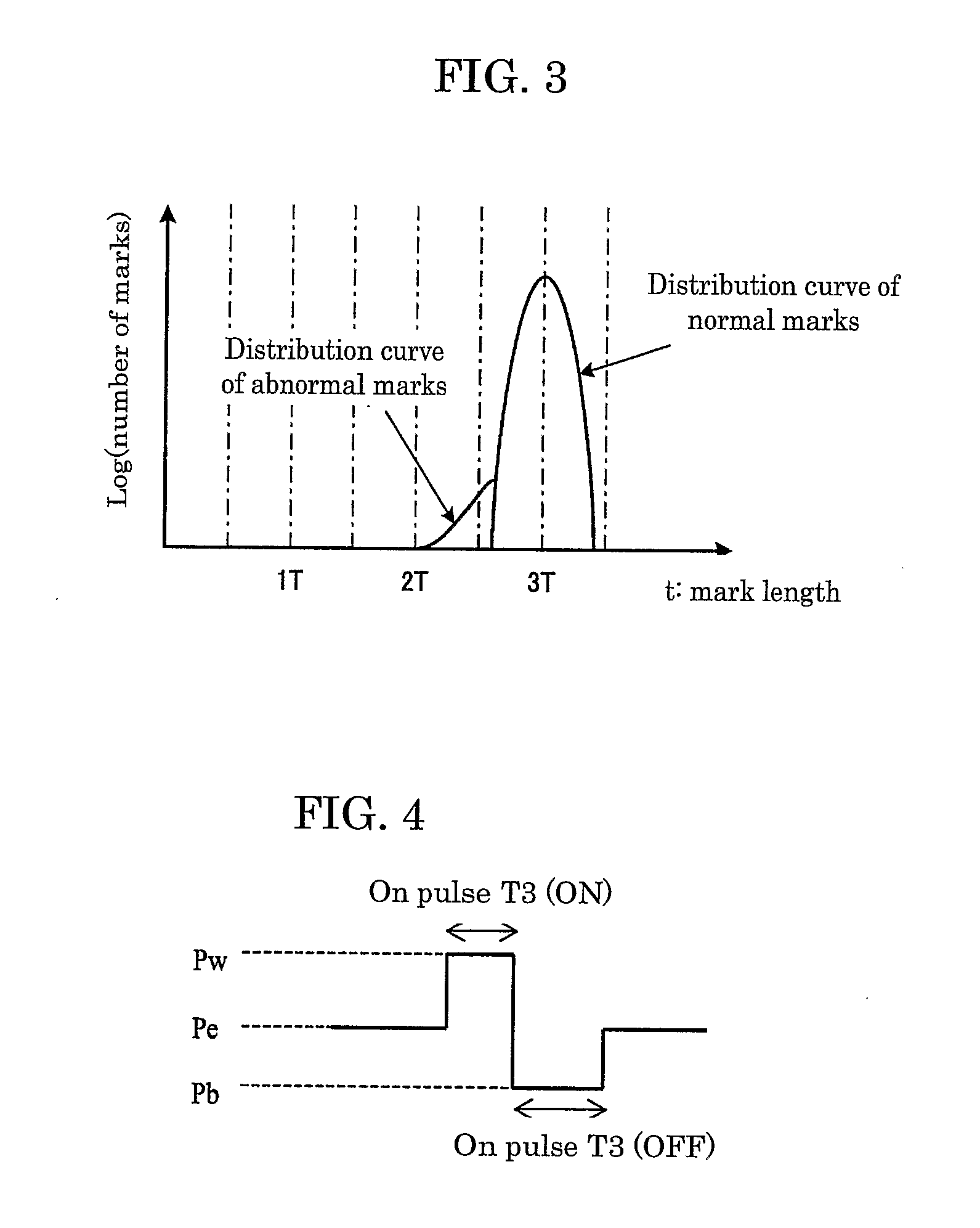
[0026]According to the aforementioned aspects, it is possible to provide an optical recording medium in which error-causing short marks are produced in numbers small enough for excellent high-recording characteristics, and an optical recording medium in which amorphous marks are uniform in shape.
[0027]In particular, according to the aforementioned aspects (4), it is possible to form uniform marks that have a large width and offer large degree of modulation.
[0028]In addition, according to the aforementioned aspects (5) and (6), it is possible to readily provide a protective layer with an average crystal particle diameter of 2 nm to 30 nm.

Problems solved by technology

Increased Sb contents, however, lead to reduction in the crystallization temperature in the recording layer and thus undesirably make the amorphous mark's shape non-uniform.
Even Sb—Te alloys, particularly those with a high Sb content, exhibit low crystalline temperatures and hence resultant amorphous marks are prone to undergo crystallization.
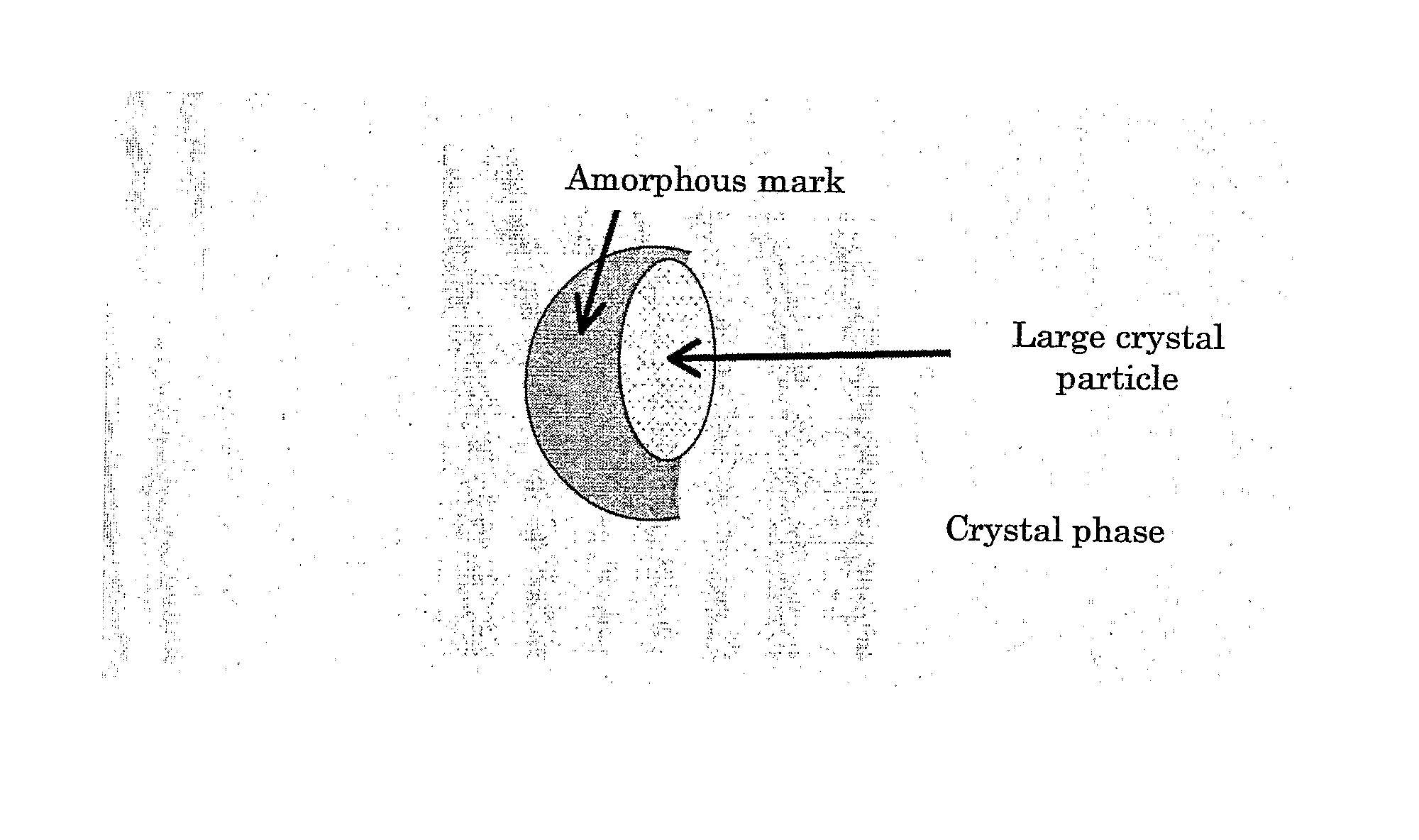
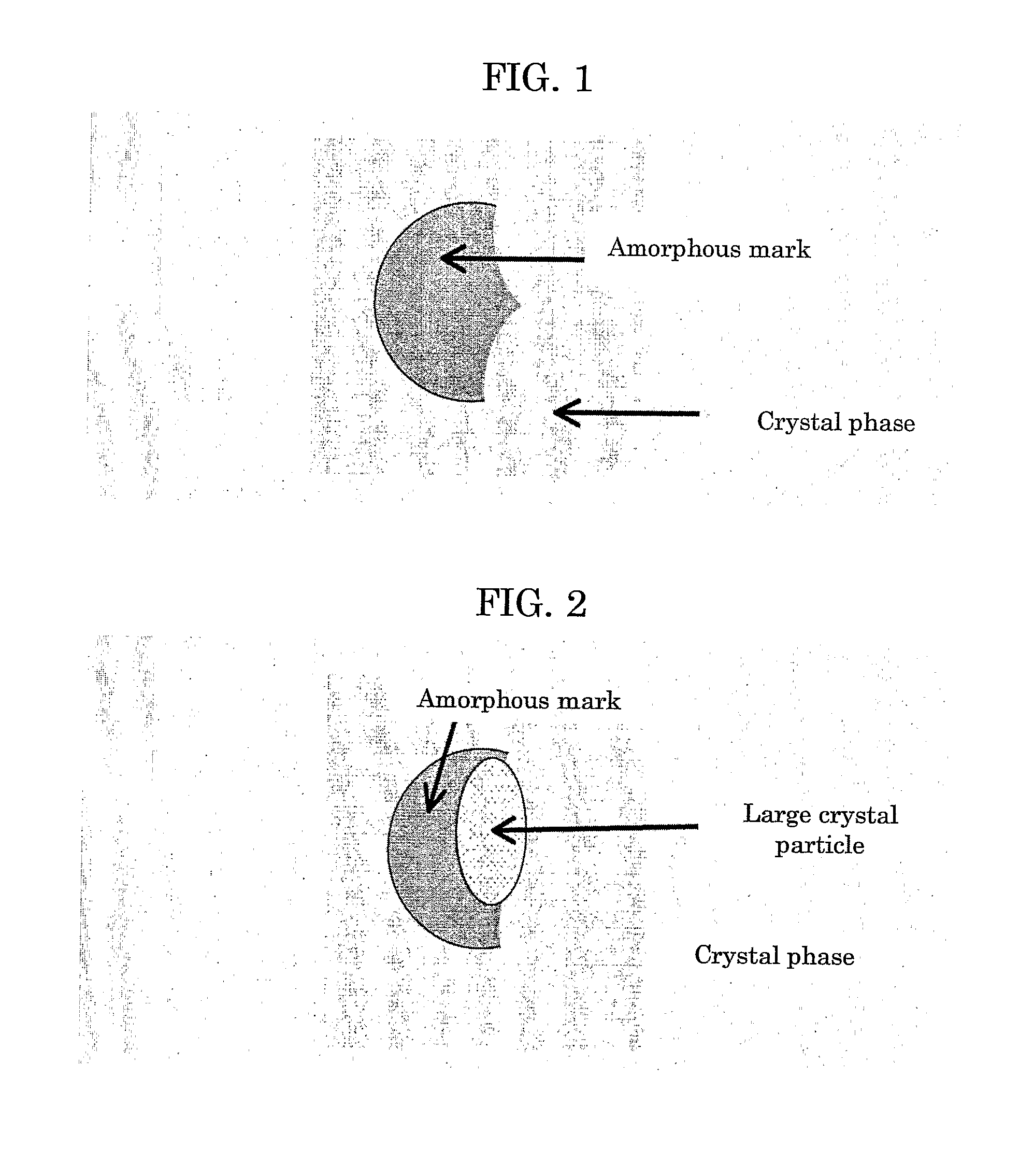
Accordingly, the use of crystalline materials for the manufacture of a protective layer significantly affects the recording layer that is in contact with the protective layer, leading to a problem that amorphous marks disappear by crystallization even in an environmental test at 70° C.

Method used


Image

  • Optical recording medium
  • Optical recording medium
  • Optical recording medium

Examples


example 1

[0053]A phase change optical recording medium (disc) was manufactured in the manner described below.

[0054]Note that sputtering was conducted using a single-wafer sputtering device (by UNAXIS) under the following condition: atmosphere=Ar gas, power=1-5 kW, Ar gas pressure=2×10⁻³ Torr. On a polycarbonate substrate that is 12 cm in diameter and 0.6 mm in thickness and has a groove of 27 nm depth and 0.74 μm track pitch, a first protective layer, a phase change recording layer, a second protective layer, and a reflective layer were sequentially deposited by means of sputtering method. The first protective layer was formed by sputtering of In2O3—SnO2 (90:10 wt %) and deposited to a thickness of 70 nm. The phase change recording layer was formed by sputtering of Sb71Sn19Ge5Ga5 (atomic %) and deposited to a thickness of 14 nm. The second protective layer was formed by sputtering of ZnS—SiO2 (80:20 mol %) and deposited to a thickness of 8 nm. The reflective layer was formed by sputtering of...

example 2

[0055]A phase change optical recording medium was produced as in Example 1 except that the first protective layer was formed using ZnS—SiO2 (80:20 mol %) and deposited to a thickness of 60 nm, the recording layer was formed using Sb75In18Zn3Ge4 (atomic %) and the second protective layer was formed using Nb2O5 and deposited to a thickness of 15 nm. Table 1 lists layer compositions of this disc.

example 3

[0056]A phase change optical recording medium was produced as in Example 1 except that the first protective layer was formed using ZnO and deposited to a thickness of 60 nm and the recording layer was formed using Sb78In18Zn4 (atomic %). Table 1 lists layer compositions of this disc.

[0057]

TABLE 1Layer constitutionFirst protectiveSecond protectiveEx.layerRecording layerlayerReflective layer1In2O3—SnO2 (70 nm)Sb71Sn19Ga5Ge5 (16 nm)ZnS—SiO2(8 nm)Ag alloy(200 nm)2ZnS—SiO2 (60 nm)Sb75In18Zn3Ge4 (14 nm)NbO2(15 nm)Ag alloy(201 nm)3ZnO (60 nm)Sb78In18Zn4 (14 nm)ZnS—SiO2(8 nm)Ag alloy(202 nm)

[0058]Initial crystallization was conducted on each of the phase change optical recording media prepared in Examples 1 to 3 using an initializing device (POP120-7AH, manufactured by Hitachi Computer Peripherals Co., Ltd.) equipped with a laser head that produces a laser beam of 810 nm wavelength and a laser spot of about 1 μm width and 75 μm length and that features a laser focusing function. Initializat...


PUM

PropertyMeasurementUnit
crystal particle diameteraaaaaaaaaa
linear velocityaaaaaaaaaa

Abstract

To provide an optical recording medium in which error-causing short marks are produced in numbers small enough excellent high-recording characteristics and in which amorphous marks are uniform in shape. The optical recording medium includes: a first protective layer; a recording layer containing Sb as a main ingredient; a second protective layer; and a reflective layer, the first protective layer, the recording layer, the second protective layer and the reflective layer being provided in the order in which light passes through the medium for recording and reproduction of information, wherein the first protective layer and / or the second protective layer, both of which are in contact with the recording layer, are / is formed of a crystalline oxide.

Description

TECHNICAL FIELD[0001]This disclosure relates to a rewritable optical recording medium with a phase change recording layer, such as Digital Versatile Disc ReWritable (DVD-RW), DVD+RW, DVD-RAM, BD-RE, and HD DVD-Rewritable.BACKGROUND ART[0002]In recent years extensive development has been in progress on optical recording media having a recording layer that is made of phase change material that enables repetitive recording. A number of phase change materials has been studied, including chalcogenide alloys such as Sn—Se—Te alloys, Sb—Te alloys, In—Se alloys, Ga—Te alloys, and Ge—Te alloys. In CD-RWs and 4×DVD+RWs, in particular, Ag—In—Sb—Te alloys are now in practical use that are obtained by addition of several different elements to Sb—Te alloys. Ag—In—Sb—Te alloys have several advantages that they readily undergo vitrification, produce uniform recording marks, are less likely to undergo composition change such as segregation and phase separation during multiple recording and erasing o...

Claims


Application Information

Patent Timeline
Patent Type & Authority Patents(United States)
IPC IPC(8): B32B3/02G11B7/24G11B7/254G11B7/257
CPCG11B7/006G11B7/243G11B7/00454G11B7/2531G11B7/2534G11B7/258Y10T428/21G11B2007/24314G11B2007/25706G11B2007/25708G11B2007/2571G11B2007/25715G11B7/259
Inventor OHKURA, HIROKOHIBINO, EIKODEGUCHI, HIROSHIITO, KAZUNORI
Owner RICOH KK
Why Eureka
Try Eureka