Liquid crystal display and method of fabricating the same

a technology of liquid crystal display and liquid crystal, which is applied in the direction of identification means, instruments, chemistry apparatus and processes, etc., can solve the problems of narrow viewing angle, low contrast, and reduced yield, and achieve uniform drying, increase cost, and avoid the effect of cleaning liquid residu

Inactive Publication Date: 2004-04-22
SHARP KK
View PDF8 Cites 89 Cited by
  • Summary
  • Abstract
  • Description
  • Claims
  • Application Information

AI Technical Summary

Benefits of technology

0148] The first measure is to completely fill the gap by a protrusion material to eliminate the cleaning liquid residue in the gap. As described above, since coating by the overcoating resin results in an increase in cost, in this embodiment, the gap is filled by the protrusion material instead of overcoating. Thus, the gap is eliminated on the CF substrate, thereby realizing uniform drying and avoiding the cleaning liquid residue.
0149] The second measure is to secure the continuous gap as is the case before by selectively removing the protrusion material on th...

Problems solved by technology

Although the TN mode liquid crystal display has advantages such as a capability of miniaturization, the TN mode liquid crystal display has disadvantages that, first, the viewing angle is narrow and, second, contrast is low.
Since the liquid crystal display using the horizontal alignment film requires to perform rubbing, damages generated by contamination or static electricity occurred during the rubbing process result in a main cause of reduction in yield.
However, although wide viewing angle can be obtained in the MVA liquid crystal display 130, an area liquid crystal molecules are not stable exists, and therefore, the problem of reduction in brightness exists.
Since this alignment defect area 40 is an area the transmissivity of the light is poor, the alignment defect area results in a reduction in brightness when the white display is performed.
In other words, the alignment of the liquid crystal molecules is disturbed in this area due to the occurrence of the lateral electric field and the like, thereby resulting in a deterioration in display characteristic of the MVA liquid crystal display 130.
If there is the level difference like this, an electric line of force concentrates at the portions, thereby causing alignment defects of liquid crystal molecules.
However, in the portions designated by the circles in FIG. 35b, there is a case when the auxiliary protrusion 20c does not sufficiently cover angular portion due to irregularities of level difference, irregularities of locations fo...

Method used


Image

  • Liquid crystal display and method of fabricating the same
  • Liquid crystal display and method of fabricating the same
  • Liquid crystal display and method of fabricating the same

Examples


sixth embodiment

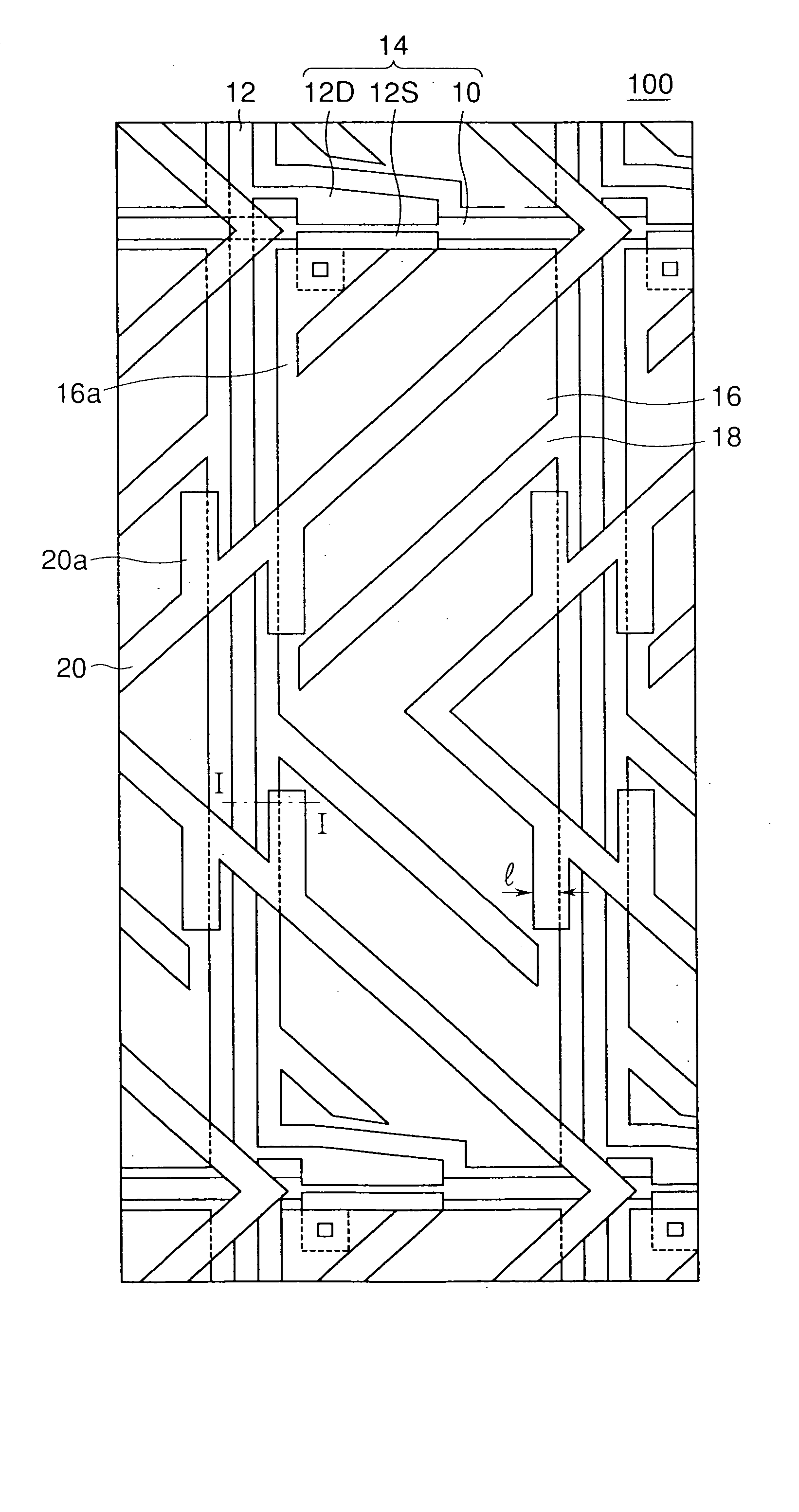
[0157] Next, a fabrication method of the liquid crystal display according to the present invention is described with reference to FIG. 18a through FIG. 20. This embodiment is according to the fifth aspect of the present invention. This embodiment is a fabrication method of the CF substrate and relates to a method of forming a spacer pattern and a protrusion pattern for alignment control of the MVA on the color filter with a photosensitive material by using photo processing.

[0158] Hitherto, when forming the protrusion pattern and the spacer pattern by a photo processing using the photosensitive material, the photo processing is required to be used in two stages since the difference between the thickness of the protrusion and the thickness of the spacer is great.

[0159] Specifically, after coating, pre-baking, exposing, developing and post-baking the photosensitive material (photo resist) on a substrate to be processed in order to form the protrusion pattern, the same photo processing ...

example 1

[0162] A case using a positive type photosensitive material is described.

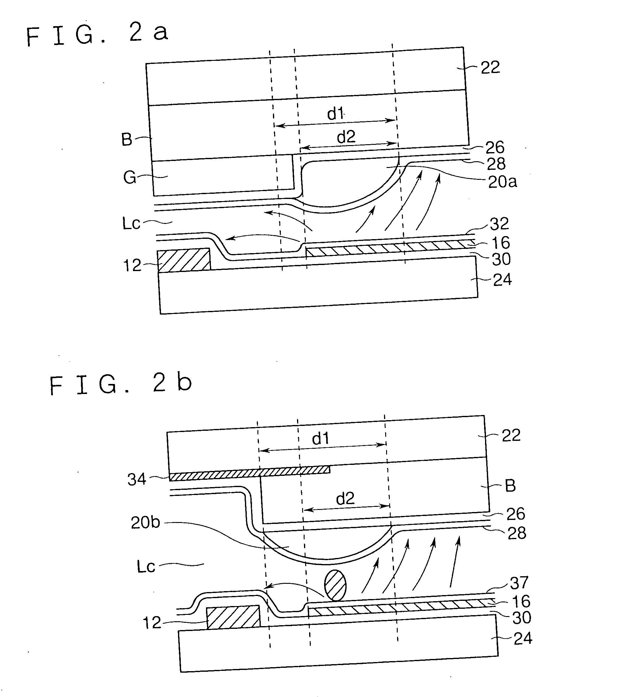
[0163] FIG. 18a shows a cross section of the CF substrate 22. A color filter for color resins R, G and B is formed on the CF substrate 22 corresponding to each pixel, and the common electrode 26 is formed on the whole surface. It will be noted that, in this example, a chrome film is used as the BM and the color filter is formed after patterning the chrome film on the CF substrate.

[0164] On a surface of the color filter on this CF substrate 22, the positive type photosensitive material 50 is coated by a spinner so that the thickness becomes equal to 4.2 .mu.m after pre-baking. A novolak type photo resist can be used as the positive type photosensitive material 50.

[0165] After pre-baking, the CF substrate 22 is put on a substrate stage of a proximity aligner, and a first mask (not shown) and the CF substrate 22 are positioned and exposed based on the BM pattern. A pattern to shade forming locations of the spacer ...

example 2

[0168] Next, the case using a negative type photosensitive material is described.

[0169] First, the same CF substrate 22 shown in FIG. 18a as in the case using the positive type photosensitive material described above is used.

[0170] On the surface of the color filter on this CF substrate 22, a negative type photosensitive material 54 is coated by the spinner so that the thickness becomes equal to 4.2 .mu.m after pre-baking. A novolak type photo resist can be used as the negative type photosensitive material 54.

[0171] After pre-baking, the CF substrate 22 is put on a substrate stage of a proximity aligner, and a third mask (not shown) and the CF substrate are positioned and exposed based on the BM pattern. A pattern in which the forming location of the spacer portion is not shaded is drawn on the third mask. Exposure is performed at an exposure value of h v (3) which allows the sufficient photosensitive material 54 to remain at exposure points by developing (FIG. 18e). In this example...


PUM


Abstract

An MVA liquid crystal display which is high in brightness and has preferable characteristics is provided. Further, the MVA liquid crystal display with a preferable display quality as well as a larger margin in fabrication and a higher yield is provided. A first substrate having a first electrode, a second substrate having a second electrode corresponding to a display pixel, the liquid crystal having negative dielectric anisotropy sealed between the first and the second substrates, and a structure which is provided on each of the first and the second substrate to control an alignment of the liquid crystal are provided. The structure in the first substrate has a linear protrusion structure and provides at least two auxiliary protrusion structures opposing to each end portion facing to the second electrode extending from a protrusion structure provided and the width between the two auxiliary protrusions and the opposing second electrode is more than 6 mum respectively.

Description

[0001] 1. Field of the Invention[0002] The present invention relates to a liquid crystal display for a television, display and the like and its fabrication method. Specifically, the present invention relates to a liquid crystal display containing a vertical alignment liquid crystal with large viewing angle and its fabrication method.[0003] 2. Description of the Related Art[0004] The liquid crystal display contains the liquid crystal inserted between a pair of substrates. Each of the pair of substrates has an electrode and an alignment film. A TN (Twisted Nematic) mode liquid crystal display widely used in the past contains the liquid crystal having a horizontal alignment film and positive dielectric anisotropy, and when no voltage is applied, the liquid crystal is aligned substantially parallel to the horizontal alignment film. When voltage is applied, the liquid crystal arises in the direction substantially perpendicular to the horizontal alignment film.[0005] Although the TN mode ...

Claims


Application Information

Patent Timeline
IPC IPC(8): G02F1/1333G09F9/30G02F1/1335G02F1/1337G02F1/1362G02F1/139
CPCG02F1/133512G02F1/133514G02F1/1337G02F1/133707G02F2201/128G02F1/136213G02F1/1393G02F2001/133776G02F2001/13712G02F1/13394G02F1/133776G02F1/13712
Inventor INOUE, HIROYASUTANIGUCHI, YOJITANAKA, YOSHINORISASAKI, TAKAHIROOKAMOTO, KENJIOTANI, MINORUSAWASAKI, MANABUFUJIKAWA, TETSUYAHAYASHI, SHOUGOSUMI, KAZUHIKOTANOSE, TOMONORI
Owner SHARP KK
Why Eureka
Try Eureka