Ultrashort pulsed laser and optical head using the same

Active Publication Date: 2004-05-06
PANASONIC CORP
View PDF14 Cites 23 Cited by
  • Summary
  • Abstract
  • Description
  • Claims
  • Application Information

AI Technical Summary

Problems solved by technology

Therefore, in order to realize the mode lock at the period of 100 MHz, the resonator length has to be set at 1.5 m. For that reason, the optical system becomes complicated as shown in FIG. 9, which causes a problem of increasing the size of the device, as we

Method used


Image

  • Ultrashort pulsed laser and optical head using the same
  • Ultrashort pulsed laser and optical head using the same
  • Ultrashort pulsed laser and optical head using the same

Examples


Example

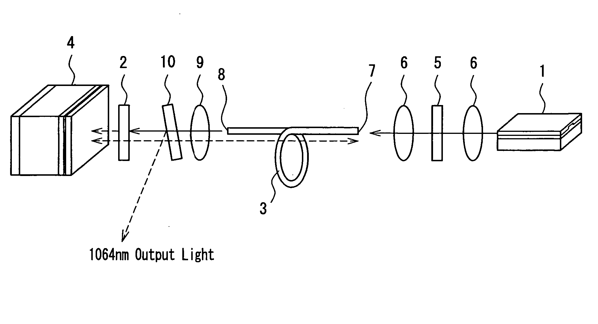
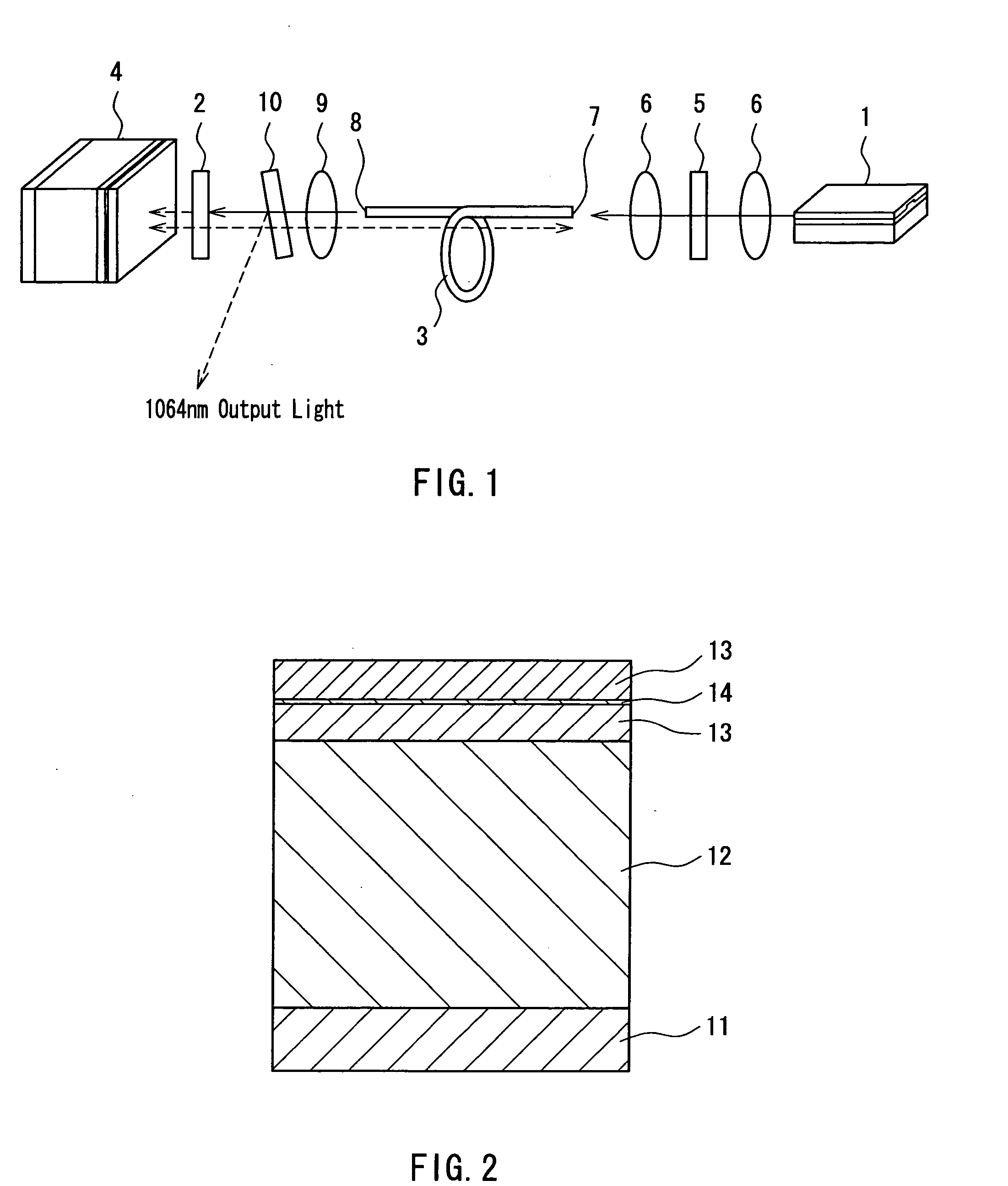
[0033] The following describes an ultrashort pulsed laser device of Embodiment 1 of the present invention, with reference to FIG. 1. This ultrashort pulsed laser device includes a pump laser diode 1, a solid laser medium 2, an optical fiber 3 and a saturable absorber mirror 4. Laser light emitted from the pump laser diode 1 is coupled with a first end face 7 of the optical fiber 3 by means of two lenses 6 with a bandpass filter 5 interposed therebetween. Laser light emitted from a second end face 8 of the optical fiber 3 passes through a lens 9 and an output mirror 10 so as to be collected onto the solid laser medium 2, where pumping occurs. The laser light passing through the solid laser medium 2 is reflected from the saturable absorber mirror 4. The saturable absorber mirror 4 and the first end face 7 of the optical fiber 3 constitute a laser resonator.

[0034] The ultrashort pulsed laser of this embodiment is intended for obtaining characteristics of a repetition frequency of sever...

Example

EMBODIMENT 2

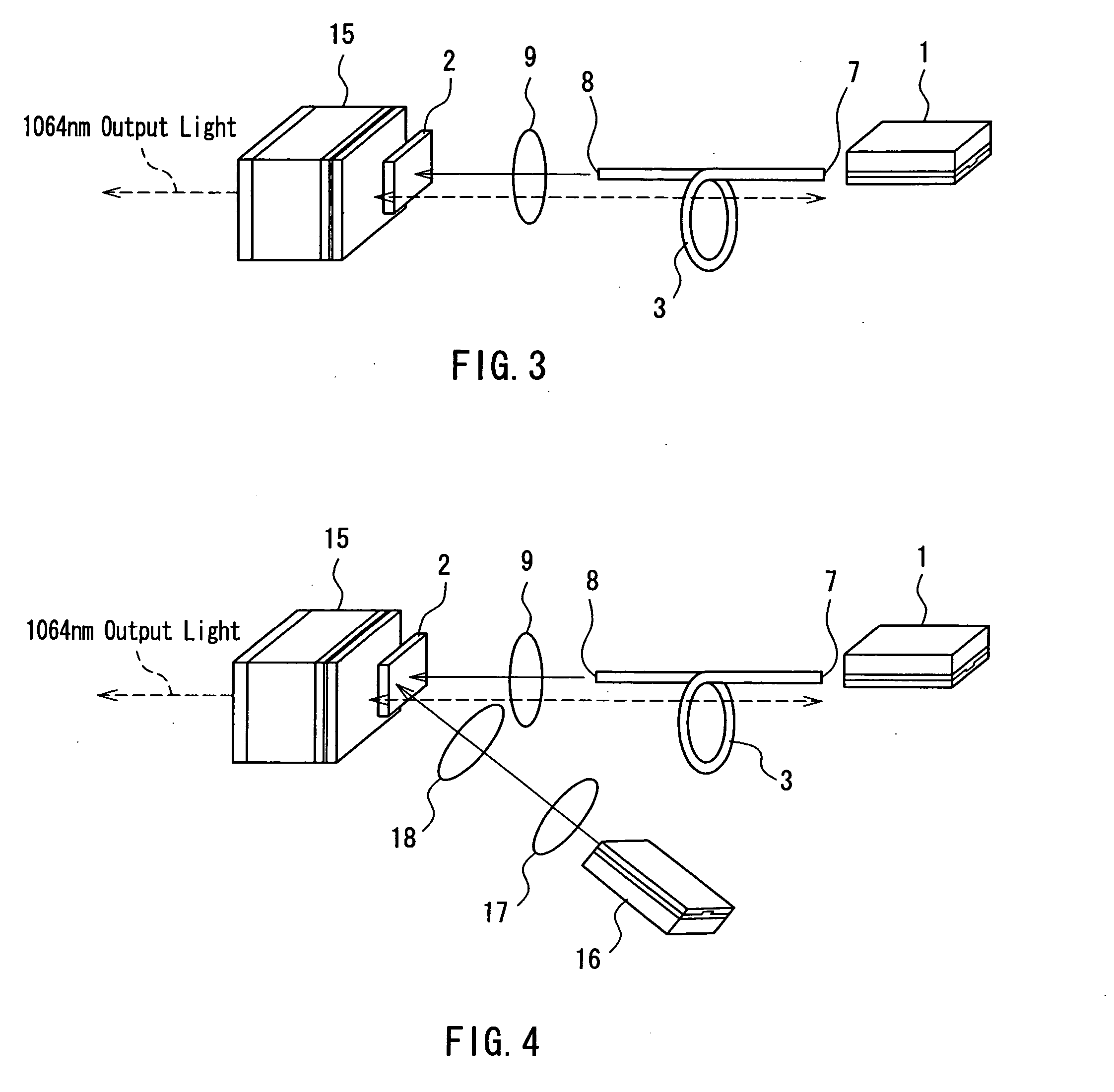
[0050] An ultrashort pulsed laser device of Embodiment 2 will be described below, with reference to FIG. 3. This device is an example to adopt a directly coupling method that does not use a coupling lens system. In this drawing, the same reference numerals are assigned to the same elements as those in FIG. 1.

[0051] A pump laser diode 1 is mounted on a Si submount with a V-shaped groove formed therein so that an active layer of the pump laser diode faces the Si submount surface. In the V-shaped groove, an optical fiber 3 also is fixed. According to this embodiment, a saturable absorber mirror 15 composed of a SESAM is used as an output mirror. A resonator with a wavelength of 1,064 nm is configured with a first end face 7 of the optical fiber 3 and the saturable absorber mirror 15, which is similar to the configuration of FIG. 1. A Bragg mirror is designed so that a reflectance of the saturable absorber mirror 15 becomes 90%. The saturated optical power obtained for the s...

Example

EMBODIMENT 3

[0054] An ultrashort pulsed laser device of Embodiment 3 will be described below, with reference to FIG. 4. In this embodiment, in addition to the pumping of Nd:YVO.sub.4 as the solid laser medium 2 via the optical fiber 3 as in the configurations of FIGS. 1 and 3, pumping light that is applied from a slanting position by a second pump laser diode 16 is collected by lenses 17 and 18. With this configuration, a higher power can be obtained. When the solid laser medium 2 is a waveguide type, pumping can be carried out by a high-powered laser diode with a wide stripe, and therefore a further higher power can be expected.

[0055] As stated above, in the configurations of the ultrashort pulsed laser devices shown in FIGS. 1, 3 and 4, the use of the optical fiber 3 allows a long resonator to be miniaturized and the mode lock frequency can be set at several hundred MHz, which is suitable for an optical recording / reproducing system. As a result, a high power at a kW level and a sh...


PUM


Abstract

An ultrashort pulsed laser device includes: a pump laser diode having linear polarization; a solid laser medium oscillating with linear polarization; an optical fiber maintaining a polarization direction; and a saturable absorber mirror. The solid laser medium is disposed between the optical fiber and the saturable absorber mirror. Laser light emitted from the pump laser diode optically is coupled with a first end face of the optical fiber, and laser light emitted from a second end face of the optical fiber pumps the solid laser medium. The first end face of the optical fiber and the saturable absorber mirror constitute a laser resonator. With this configuration, mode lock can be realized stably at a repetition frequency of several hundred MHz.

Description

[0001] 1. Field of the Invention[0002] The present invention relates to an ultrashort pulsed laser device used in an optical communication field and an optical information processing field.[0003] 2. Related Background Art[0004] Three-dimensional bit-by-bit recording, which is a technology expected as next generation high-density and high-capacity recording, exploits a non-linear effect such as a multiphoton process. When ultrashort pulsed laser with a pulse width in femtoseconds is collected onto a glass, an organic material and the like that are transparent with respect to laser light applied in a normal state using a lens, a transition probability of the absorption changes in proportion to the square of a light intensity, thus generating optical absorption. Thereby, the absorption spectrum can be changed by, for example, changing diarylethene from an open ring to a closed ring. Since the material is transparent with respect to laser light, it can be made a multilayer along a lamin...

Claims


Application Information

Patent Timeline
IPC IPC(8): G11B7/00G11B7/12H01S3/0941H01S3/098H01S3/10
CPCH01S3/1118H01S3/09415
Inventor KITAOKA, YASUOYAMAMOTO, KAZUHISA
Owner PANASONIC CORP
Why Eureka
Try Eureka