
Conductance valve and pressure-to-conductance transducer method and apparatus

a technology of pressure-to-conductance transducer and valve, which is applied in the direction of fluid pressure measurement, liquid/fluent solid measurement, peptide measurement, etc., can solve the problems of inability to easily restore the flow of liquid, impracticality of valve, and difficulty in using mechanical valves for microfabricated microfluidic networks

Inactive Publication Date: 2004-05-27
SANDIA NAT LAB
View PDF8 Cites 12 Cited by
  • Summary
  • Abstract
  • Description
  • Claims
  • Application Information

AI Technical Summary

Problems solved by technology

Although miniature valves are common, all examples known to the Applicants have dead volumes that are one or more orders of magnitude too large for use in the proposed microfluidic network.
Numerous problems with tolerances, stiction, and limitations of micromachining materials and methods make the use of a mechanical valve extremely challenging for microfabricated microfluidic networks.
However, given the dangers of gas bubbles becoming entrained in the solution and / or migrating uncontrollably, localization and reversibly of bubble formation is absolutely essential.
However, such a valve is impractical in a typical liquid that includes dissolved gas because flow of liquid cannot easily be restored.
That is, the prior art provides no teaching for how a gas bubble could be reversibly created and extinguished nor how its position could be maintained to provide process localization.
Furthermore, the means taught by these references for creating and elimination bubbles is limited to the use of a heater element.
Although such an approach may be possible, the complexities of such a micro-machined design are considerable.
However, this creates a danger of outgassing at some other point in the network, and highly soluble gasses (e.g., ammonia) may greatly disrupt the pH or other properties of the solution.
Limiting or breaking the contiguity of the fluid filling the channels throttles or blocks both current flow and electrokinetic transport through the channel (assuming the interior walls of the microfluidic network are non-conducting; if they are conductive, the EK valve may only disrupt electrokinetic transport).
However, the need for providing high temperatures severely limits the range of applications for which this approach is suitable.
Failure to maintain this minimum pressure gives rise to an un-wetted, or "dry," region along the length of column bed.
Further reducing the pressure and / or increasing the temperature increases the de-wetting threshold size, de-wetting a larger fraction of the pores, and further lowers the material conductance.
Subsequent cycles of depressurization and repressurization, therefore, lead to large, cyclical changes in the conductivity of the porous matrix.
In this case, even a complete vacuum behind the meniscus is incapable of halting its retreat.
Increasing the applied pressure, however, reduces the critical pore size meaning that for a given pore geometry the entrained fluid will de-wet below a critical applied pressure and re-wet above a critical applied pressure.
Because the dynamics of the bubble growth is uncertain, the temperature local to the meniscus, and hence the bubble vapor pressure is uncertain.
Moreover, without this isolation means, it may not be possible to create a low enough pressure in the valve to allow de-wetting the packed porous region when the pathway into which the valve is inserted is under an applied hydrostatic pressure.
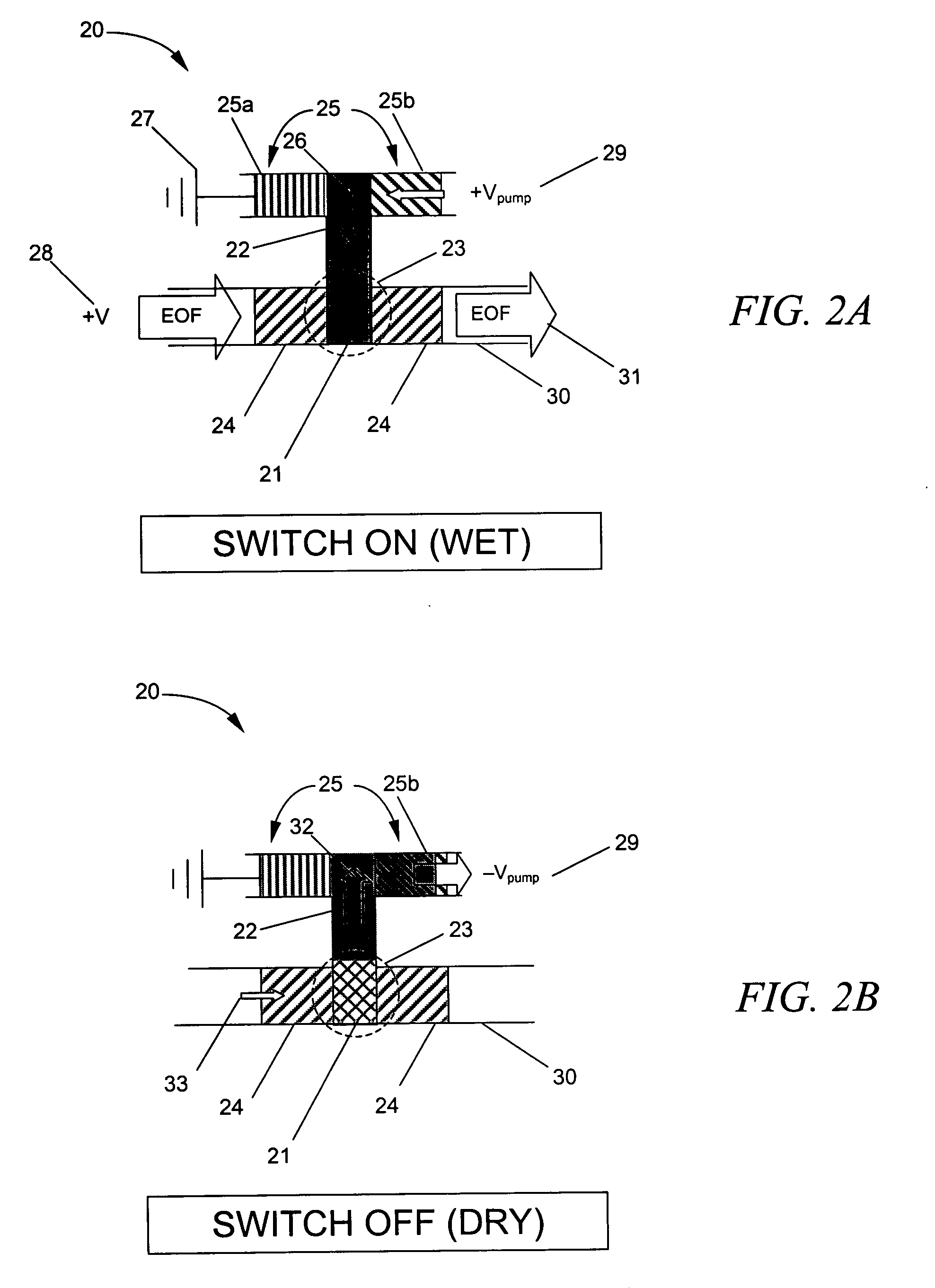
Sufficiently high pressures in channel 30 can overwhelm the valve actuator pressures, causing re-wetting and defeating the efficacy of valve 20.

Method used


Image

  • Conductance valve and pressure-to-conductance transducer method and apparatus
  • Conductance valve and pressure-to-conductance transducer method and apparatus
  • Conductance valve and pressure-to-conductance transducer method and apparatus

Examples


Embodiment Construction

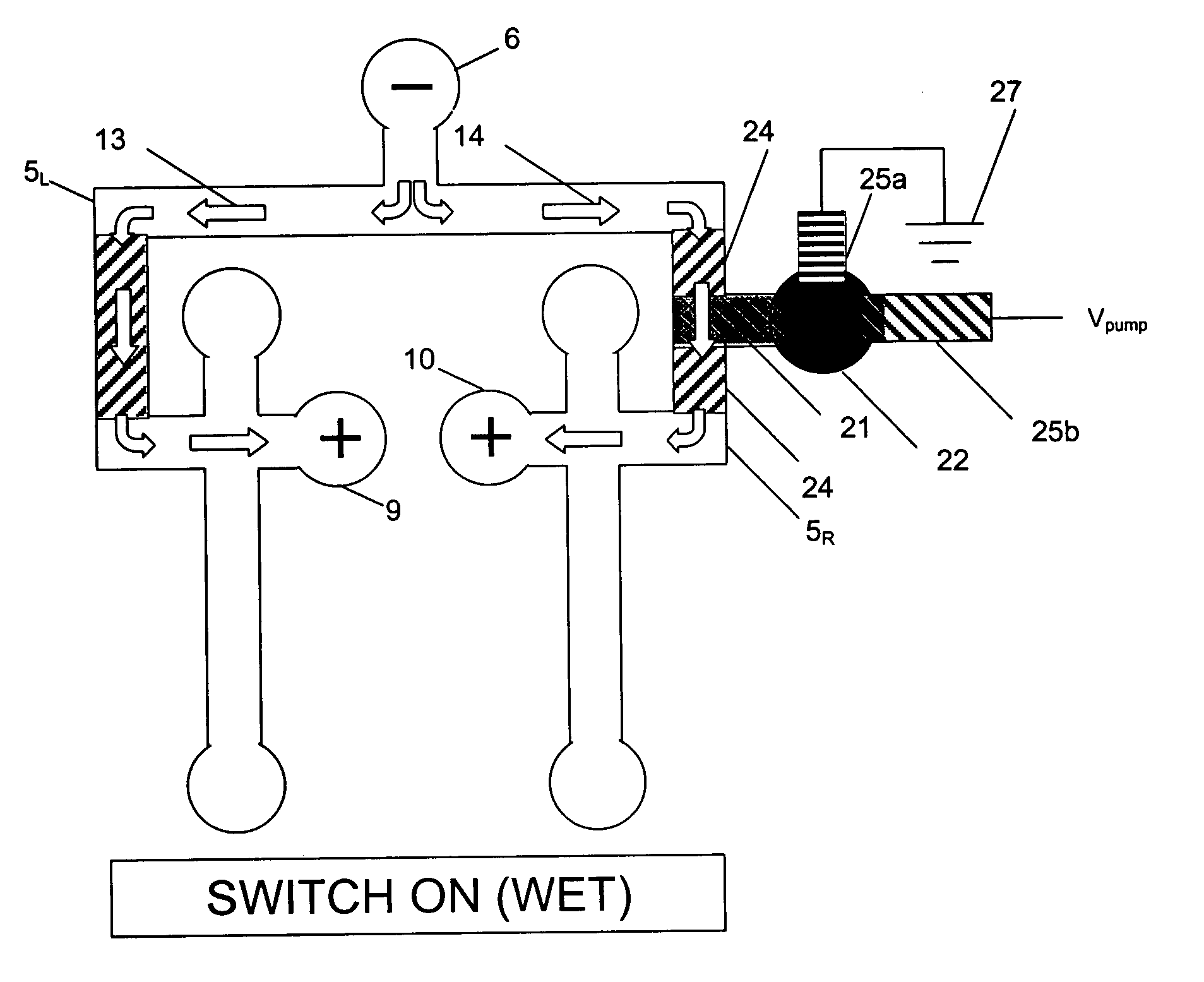
[0056] Before describing specific experimental results, it is useful to describe some of the considerations concerning the use of such a device in an electrokinetic microfluidic network, and the materials from which such a device can be made. Although the device could be demonstrated with a large variety of different media or materials for providing a matrix of hydrophobic pores, the device of the present invention was constructed using packed beads of PTFE resin (DuPont TEFLON.RTM.) as the porous matrix. (Also useful are acetal resins, such as DuPont DELRIN.RTM., and polytrifluorochloroethylene resins, such as 3M Kel-Fe.RTM..) PTFE is chosen, however, because it has the following properties that are generally desirable for a device of this type, i.e., a conductivity switch, so that it may be interposed in a microfluidic network without otherwise disrupting its performance:

[0057] PTFE provides a matrix through which molecules can be pumped (hydraulically or electrokinetically) witho...


PUM

PropertyMeasurementUnit
Pore sizeaaaaaaaaaa
Pressureaaaaaaaaaa
Electrical conductivityaaaaaaaaaa

Abstract

A device for interrupting or throttling undesired ionic transport through a fluid network is disclosed. The device acts as a fluid valve by reversibly generating a fixed "bubble" in the conducting solvent solution carried by the network. The device comprises a porous hydrophobic structure filling a portion of a connecting channel within the network and optionally incorporates flow restrictor elements at either end of the porous structure that function as pressure isolation barriers, and a fluid reservoir connected to the region of the channel containing the porous structure. Also included is a pressure pump connected to the fluid reservoir. The device operates by causing the pump to vary the hydraulic pressure to a quantity of solvent solution held within the reservoir and porous structure. At high pressures, most or all of the pores of the structure are filled with conducting liquid so the ionic conductance is high. At lower pressures, only a fraction of the pores are filled with liquid, so ionic conductivity is lower. Below a threshold pressure, the porous structure contains only vapor, so there is no liquid conduction path. The device therefore effectively throttles ionic transport through the porous structure and acts as a "conductance valve" or "pressure-to-conductance" transducer within the network.

Description

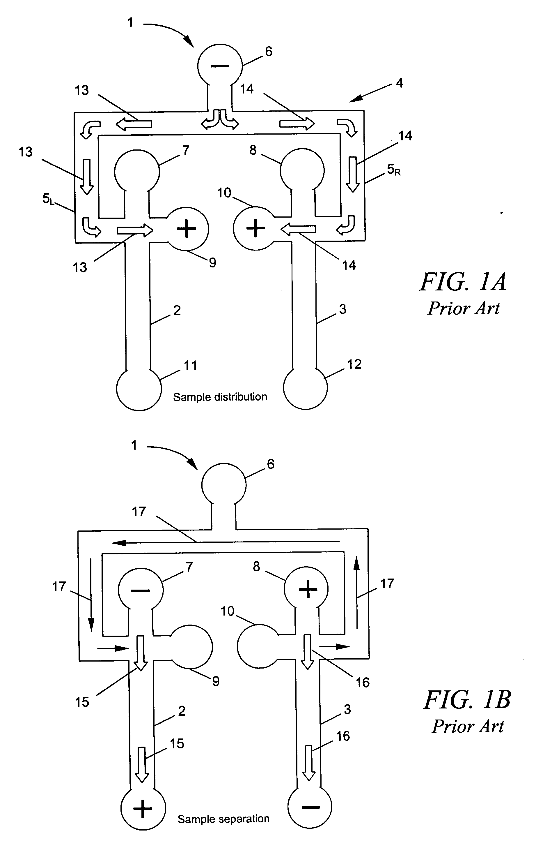
[0002] 1. Field of the Invention[0003] The present invention relates to a method for controlling undesirable flow of charged species across, or between, regions of a fluid network such as a separation network. Such systems typically comprise multiple separation channels connected by a common manifold and in those systems where separation is driven by an electrical gradient (electrokinetic pumping), a means for uncoupling species transport between channels is desirable.[0004] Integrated microfluidic networks used for analytical microseparations generally rely on electrokinetic phenomena for control of material transport through the channels. A recurring network topology consists of a distribution manifold connected to many parallel channels. This arrangement, shown schematically in FIGS. 1A and 1B for the case of two channels, enables a common buffer solution or sample to be distributed to all channels, but then allows individual channels to perform different functions.[0005] FIGS. 1...

Claims


Application Information

Patent Timeline
IPC IPC(8): F15C5/00F16K99/00
CPCF15C5/00F16K99/0001F16K99/0057F16K99/0019F16K99/0017Y10T137/2076Y10T137/2082Y10T137/2191Y10T137/2196
Inventor SCHOENIGER, JOSEPH S.CUMMINGS, ERIC B.BRENNAN, JAMES S.
Owner SANDIA NAT LAB
Learn More