Ionically conductive polymers for use in fuel cells

a technology of ionically conductive polymers and fuel cells, applied in the field of polymers, can solve the problems of consumption of cell power, and achieve the effect of enhancing the acidity of the polymer

Inactive Publication Date: 2011-03-01
BATTELLE MEMORIAL INST
View PDF8 Cites 6 Cited by
  • Summary
  • Abstract
  • Description
  • Claims
  • Application Information

AI Technical Summary

Benefits of technology

[0012]In another embodiment, an ionically conductive polymer for use as a binder in a fuel cell electrode has ion exchange groups and also has electron withdrawing groups attached to the ion exchange groups to enhance the acidity of the polymer. The polymer has a pKa not greater than about 2.0.

Problems solved by technology

The electrons, which cannot pass through the membrane, flow from the anode to the cathode through an external circuit containing an electric load, which consumes the power generated by the cell.

Method used


Image

  • Ionically conductive polymers for use in fuel cells
  • Ionically conductive polymers for use in fuel cells
  • Ionically conductive polymers for use in fuel cells

Examples


example 1a

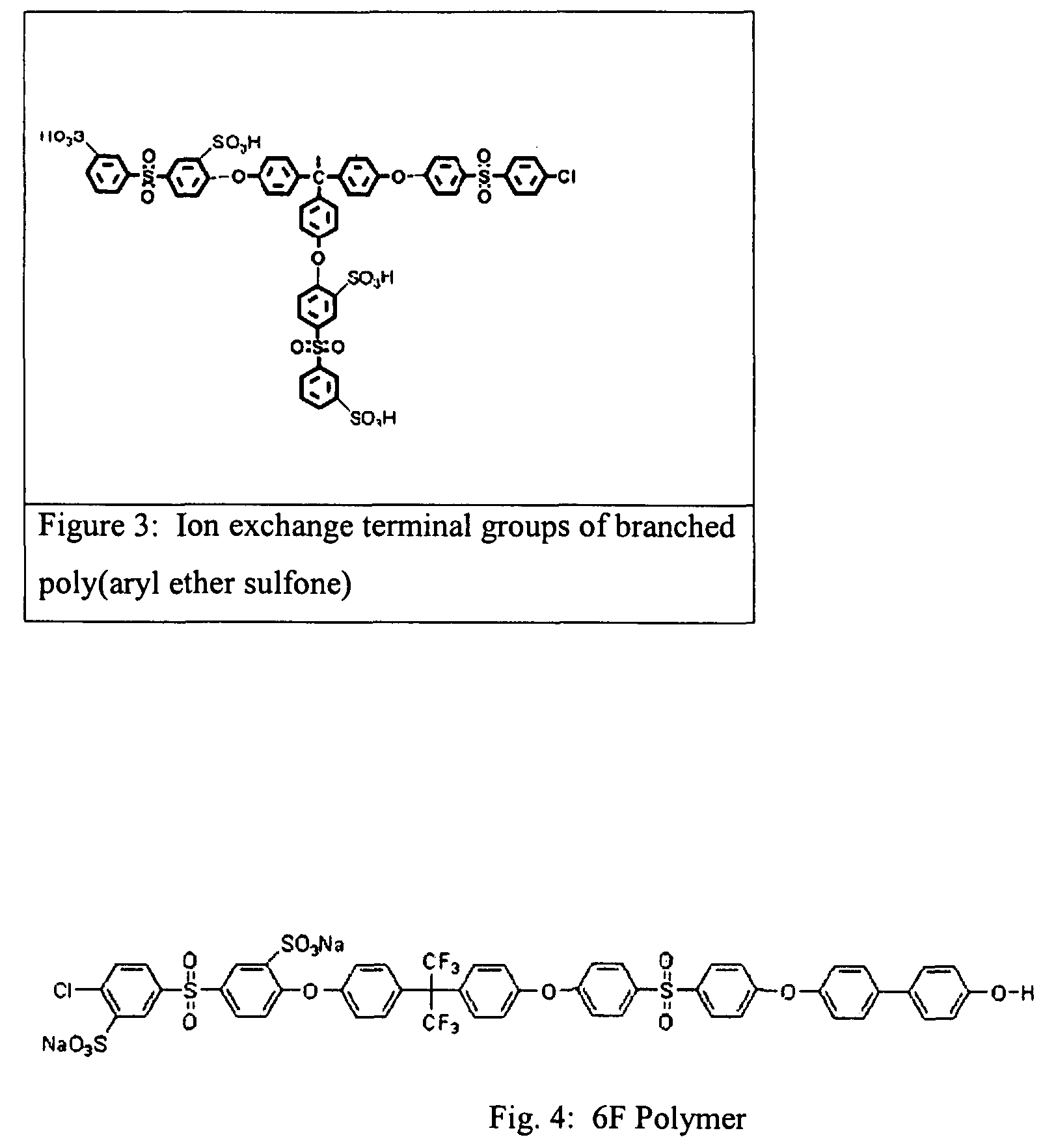
[0029]The polymer shown in scheme 1 was obtained as follows. In a 250 mL three neck round bottom flask, fitted with a stir rod, thermocouple, Dean Stark condenser and inlet for gas purging, charged 10.2 grams of Sulfonated poly(aryl ether sulfone) with degree of sulfonation=50%, K2CO3 (3.1 gram) 75 mL N,N-dimethylacetamide and 35 mL toluene. The reagents were heated slowly until the reflux temperature reached (˜133° C.) and maintain the reflux for 4 hours. Toluene was gradually removed and increased the temperature to 160° C. and removed the remaining toluene. The flask was cooled to 60° C. and added 10.1 of diglycidylether terminated poly(dimethyl siloxane) with number average molecular weight 5000 over a period of one hour. The flask was slowly heated to 120° C. and reaction was maintained for 12 h at that temperature. At the end of 12 h, the reaction mixture was cooled down to room temperature. The product obtained was isolated by precipitating in water and drying in a vacuum ove...

example 1b

[0030]In a 500 mL three neck round bottom flask, fitted with a stir rod, thermocouple, Dean Stark condenser and inlet for gas purging, charged 22.3 gram of Sulfonated poly(aryl ether sulfone) with degree of sulfonation=50%, 250 mL N,N -dimethylacetamide and 70 mL toluene. The reagents were heated slowly until the reflux temperature reached (˜133° C.) and maintain the reflux for 4 hours. Toluene was gradually removed and increased the temperature to 160° C. and removed the remaining toluene. The flask was cooled to 20° C. and added 7 mL n-butyl lithium followed by 8.9 g of chlorine terminated poly(dimethyl siloxane) with number average molecular weight 3000 a period of 20 to 30 minutes. The reactants were allowed to stir at room temperature for 16 hours and the product obtained was isolated by precipitating in isopropanol followed drying in a vacuum oven at 120° C. for 24 h.

example 1c

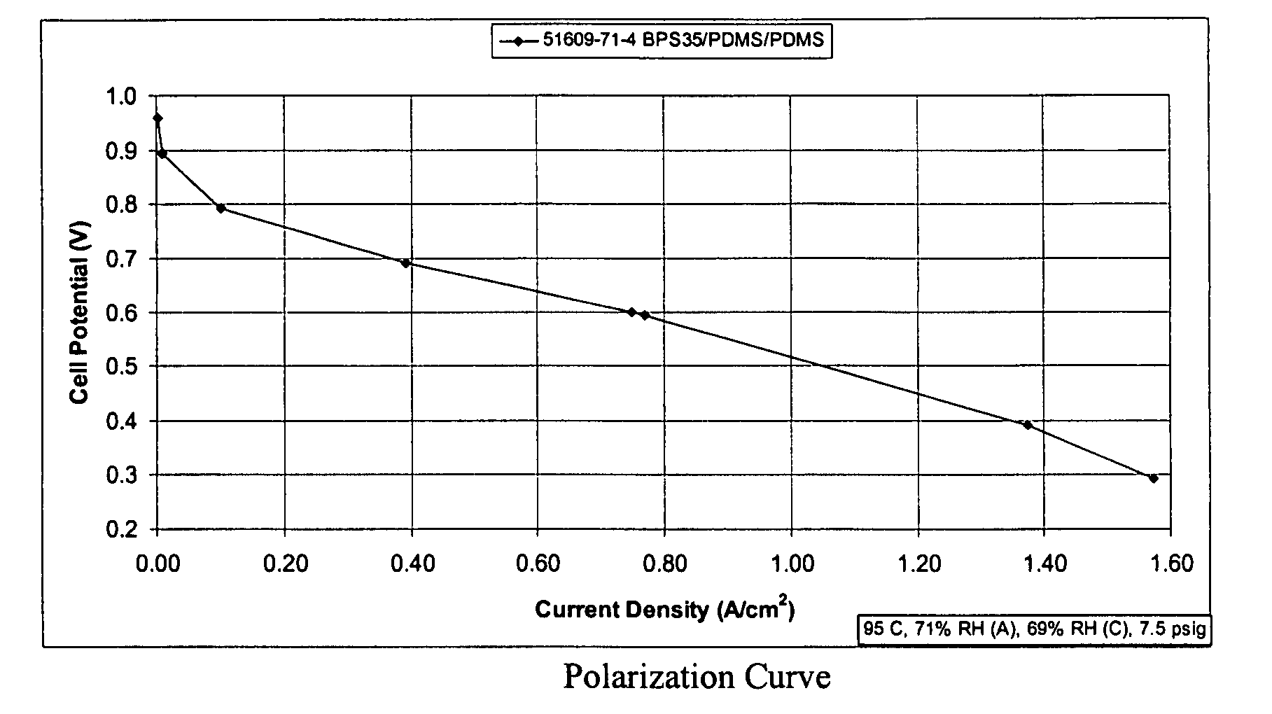
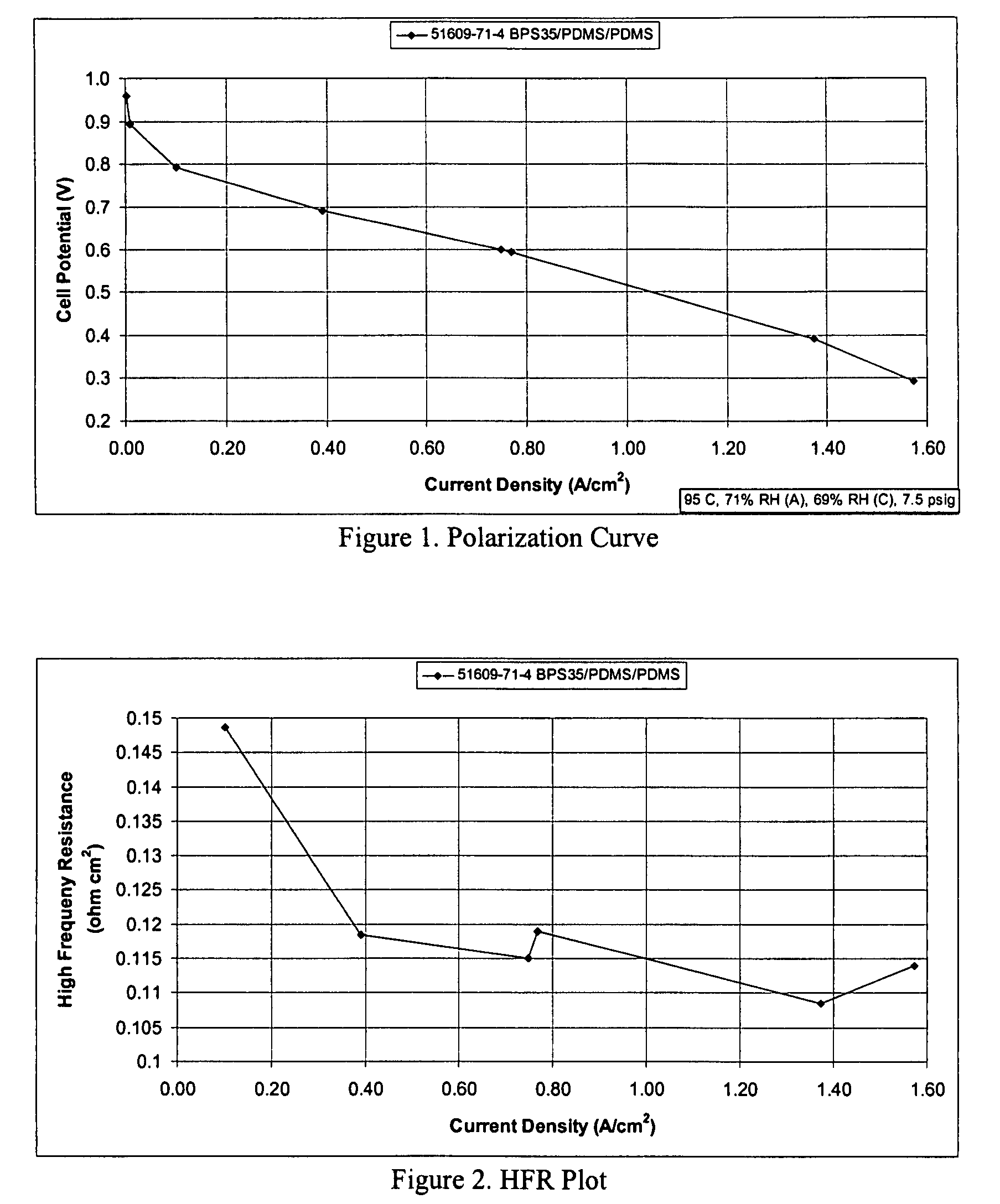
[0031]In a 250 mL three neck round bottom flask, fitted with a stir rod, thermocouple, Dean Stark condenser and inlet for gas purging, charged thoroughly dried 25.1 gram of Sulfonated poly(aryl ether sulfone) with degree of sulfonation=35%, 150 mL N,N-dimethylacetamide. The reagents were heated slowly up to 125 deg C. and stirred until all the polymer is completely dissolved in the solvent. The flask was cooled to 20° C. and added 9 mL n-butyl lithium followed by 8.3 g of chlorine terminated poly(dimethyl siloxane) with number average molecular weight 3000 over a period of 20 to 30 minutes. The reactants were allowed to stir at room temperature for 16 hours and the product obtained was isolated by precipitating in isopropanol followed drying in a vacuum oven at 120° C. for 24 h.


PUM

PropertyMeasurementUnit
temperatureaaaaaaaaaa
ionic conductivityaaaaaaaaaa
crystallinity indexaaaaaaaaaa

Abstract

An ionically conductive polymer is a copolymer including first and second polymer segments. The first polymer segments have a hydrophobic character and a high oxygen permeability. The second polymer segments have a hydrophilic character and a low oxygen permeability. The copolymer has an ionic conductivity of at least about 1×10⁻⁵ S / cm at any point within a temperature range of from 30° C. to 150° C. and a relative humidity range of from 20% to 100%. The ionically conductive polymer can be used in an electrochemical device such as a fuel cell, for example, used as a binder in an electrode or used to produce a membrane.

Description

BACKGROUND OF THE INVENTION[0001]This invention relates in general to polymers, and in particular to ionically conductive polymers for use in fuel cells and other electrochemical devices. For example, the polymers may be used as binders in fuel cell electrodes and / or for producing fuel cell membranes.[0002]A fuel cell is an electrochemical device that continuously converts chemical energy into electric energy and some heat for as long as fuel and oxidant are supplied. Fuel cells are evolving. Some currently known categories of fuel cells include polymer electrolyte membrane (PEM), alkaline, phosphoric acid, molten carbonate, solid oxide, and microbial / enzyme based.[0003]At the heart of the PEM fuel cell is a membrane electrode assembly (MEA). The MEA includes a membrane made from a polymer electrolyte or proton conducting polymer. The polymer electrolyte membrane is sandwiched between a pair of electrodes called an anode and a cathode. The MEA also usually includes porous, electrica...

Claims


Application Information

Patent Timeline
Patent Type & Authority Patents(United States)
IPC IPC(8): C08J5/20H01B1/04H01M8/10
CPCC08G65/38C08G65/40C08G75/23C08G77/28C08G77/392C08J5/2256H01M4/8668H01M8/1032H01M8/1037H01M8/1044H01M8/1067C08G2650/56C08J2371/12C08J2381/06C08J2383/12C08L2205/05H01M2300/0082Y02E60/521Y02E60/50
Inventor SAYRE, JAY R.LALGUDI, RAMANATHAN S.VIJAYENDRAN, BHIMA R.
Owner BATTELLE MEMORIAL INST
Why Eureka
Try Eureka