
Glassy carbon thermoplastic compositions

a technology of glassy carbon and compositions, applied in the field of polymer compositions, can solve the problems of poor energy absorption of pets, negative effect on the visual appearance of pet bottles, darkening, becoming less bright and more hazy, etc., and achieves good reheating rate, improved l* and b* ratings, and low coefficient of static friction

Inactive Publication Date: 2004-05-27
EASTMAN KODAK CO
View PDF23 Cites 74 Cited by
  • Summary
  • Abstract
  • Description
  • Claims
  • Application Information

AI Technical Summary

Benefits of technology

[0008] We have discovered a thermoplastic composition having a good reheat rate with improved L* and b* ratings. We have also discovered a thermoplastic composition which has a low coefficient of static friction and a good reheat rate. We have also discovered a thermoplastic composition with a good reheat rate and low sidewall bottle haze.
[0022] The invention also includes an embodiment wherein there is provided a polyester composition comprising an additive in an amount ranging from 50 ppm to 150 ppm which functions to increase the reheat rate of the composition by at least 2.5.degree. C. for the first 50 ppm of additive and reduces the coefficient of static friction of the composition by at least 20% for the first 50 ppm of additive, each relative to a composition without said additive, wherein the composition has a haze value of less than 9%, and preferably a bottle sidewall haze value of 5% or less.

Problems solved by technology

However, PET absorbs energy poorly in the region of 500-2000 nm.
Unfortunately, these materials also have a negative effect on the visual appearance of the PET bottle, causing it to darken and become less bright and more hazy.
The amount of absorbing compounds that can be added to a polymer is limited by its impact on the visual properties of the polymer, such as brightness, which is a measure of transparency, and color.
The disadvantage of these additives is that cause a significant loss in brightness and / or clarity in the resin.
Efforts to reduce the stickiness of bottles through the incorporation of additives such as fumed silica, amorphous silica, and talc have successfully reduced the coefficient of static friction relative to a control without an anti-stick additive, but some anti-sticky additives tend to remarkably decrease the brightness of the preforms and / or significantly increase haze.

Method used


Image

  • Glassy carbon thermoplastic compositions
  • Glassy carbon thermoplastic compositions
  • Glassy carbon thermoplastic compositions

Examples


example 1

[0124] In this example, SGC2 reheat additive is compared to a BIO control. The reheat additives were combined with Base PET4 by the following method in the amounts shown in Table 1. Prior to any mixing the Base PET4 pellets were ground to a powder and dried at 150.degree. C. for 8 hours in a Conair.RTM. dehumidifying dryer. Each subsequent sample was prepared by dry blending the powder of Base PET4 with the appropriate level of reheat additive followed by hand mixing in a polyethylene bag. The mixture was then added to the feed hopper of a twin screw extruder, fitted with a set of high shear mixing screws. The extruder's vent was plugged and nitrogen was continuously fed to the feed hopper and extruder throat to exclude air. The extruder was operated at a screw speed of 200 rpm and a temperature of approximately 282.degree. C. Under these conditions the polymer residence time in the extruder's barrel was approximately three minutes. The extrudate was quenched in an ice water bath an...

example 2

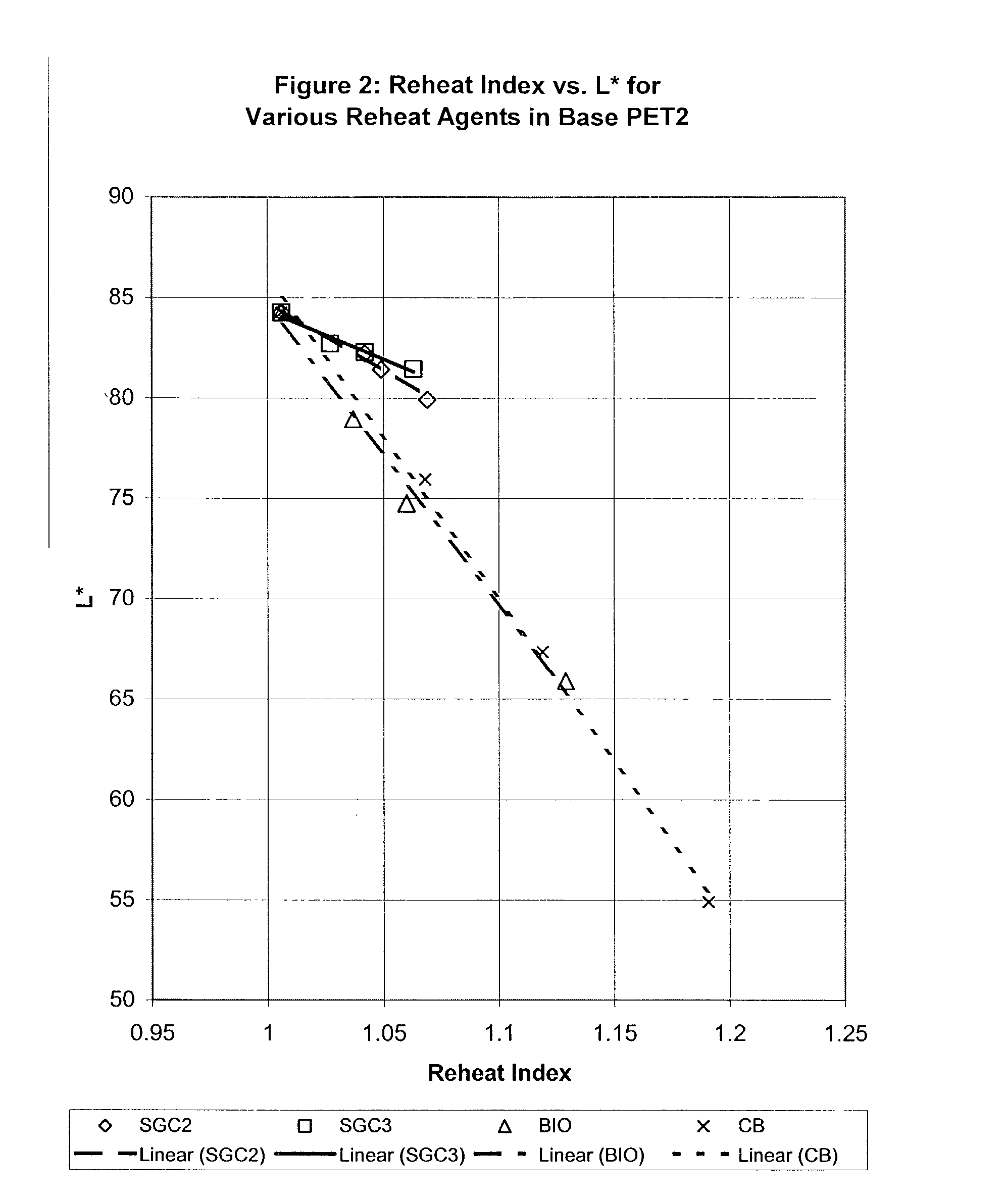
[0127] The purpose of this example is to compare SGC2 and SGC3 reheat additives to BIO and CB reheat additives. Blends of these additives in Base PET2 were prepared in the following manner. Each additive was dry blended in a glass bottle with Base PET2 that had been cryogenically ground to a particle size that was small enough to pass through a sieve with 3-mm diameter circular holes. The reheat additive loading in this concentrate mixture was 0.2 weight percent. The mixture was dried at 110.degree. C. overnight in a vacuum oven at a pressure of less than thirty inches of water. The dry mixture was melt blended in a DACA.RTM. MicroCompounder / MicroInjector, using a screw temperature of 290.degree. C. and a screw speed of 120 rpm. The mixture was circulated in the instrument for two minutes and then extruded. The resulting extrudate was cryogenically ground in a Wiley mill to produce a powder small enough to pass a screen with 3-mm diameter holes. This final melt concentrate was then ...

example 3

[0134] Lab-scale polymer preparations were made to evaluate the impact of prolonged exposure of the SGC additive to typical PET manufacturing conditions of temperature and pressure. The general synthetic procedure is described below for the preparation of a Base PET5. This example also demonstrates the addition of the reheat additive to a polyethylene terephthalate process in the melt phase at the prepolymer stage of manufacture before polycondensation in a finishing stage. Polymers prepared via this route were used to prepare discs for evaluation of color, reheat and haze values. The reheat additives evaluated in this manner were: SGC1 (0-150 ppm), SGC2 (0-200 ppm), CB (0-10 ppm), GR(0-150 ppm) and RA. RA was formed in-situ by the addition of phosphorous acid reducing agent.

[0135] A typical charge of reactant to a 5-L three-necked round bottom flask is shown in the table below.

3 Reactant Amount (grams) Dimethyl terephthalate 1941.9 Ethylene glycol 1230.23 1,4-Cyclohexanedimethanol ...


PUM

PropertyMeasurementUnit
Lengthaaaaaaaaaa
Lengthaaaaaaaaaa
Fractionaaaaaaaaaa

Abstract

A thermoplastic composition such as a polyester composition including polyethylene terephthalate polymers containing glassy carbon, and the preforms, bottles, sheets, rods, tubes, films and other articles made from these compositions. Also, polyester compositions are provided which have a certain individual or combination of properties, including low coefficient of static friction, low coefficient of static friction and low haze or high L* or low positive b* or a combination thereof, and those having low L* and low positive b* at given reheat rates.

Description

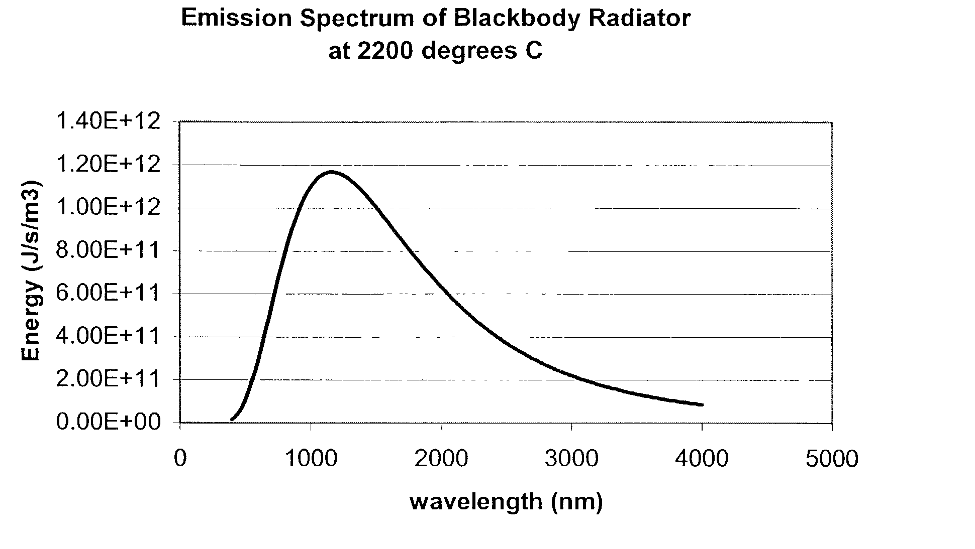
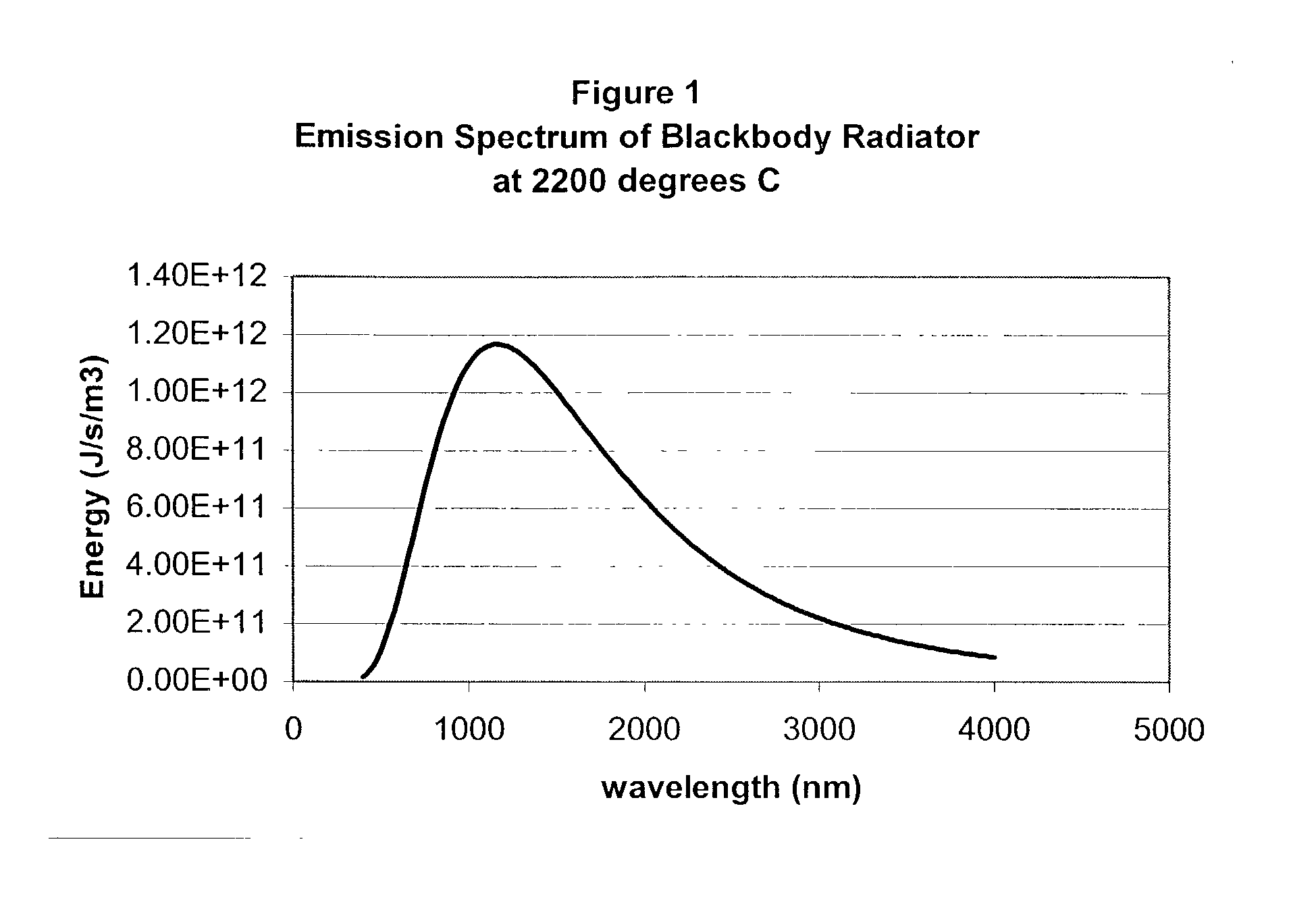
1. BACKGROUND OF THE INVENTION[0001] The use of polymer compositions, particularly compositions comprising poly(ethylene terephthalate) or copolymers thereof (hereinafter collectively referred to as "PET"), for example in the form of films, bottles and other containers is well known. When bottles or other containers (hereinafter collectively referred to as "containers") are used for containing fluids, e.g., water, juices and carbonated drinks, container-forming compositions, in the form of polymer chips or pellets, are usually formed into the container shape in a two stage process. First, a tube-shaped preform is injection molded. Second, the preform is heated above its glass transition temperature and blown into a mold with high pressure air in order to shape it into a bottle.[0002] A quartz infrared lamp is used to "reheat" the preform in the second stage. Typical lamp temperatures are 2000-3000 K, having a broad emission spectrum in the range of 500 to 2000 nm. The maximum light ...

Claims


Application Information

Patent Timeline
IPC IPC(8): B29B11/08C08J5/00B29C45/00B29C49/06B29K67/00B29L22/00C08K3/04C08K7/18C08L67/00
CPCB29B2911/1402B29B2911/14026B29B2911/14033B29B2911/1404Y10T428/1352B29B2911/14133C08K3/04C08K7/18C08K2201/016B29B2911/14106Y10T428/31786B29C2949/26B29C2949/28B29C2949/24B29C2949/22B29C2949/3024B29C2949/3032C08L67/02C08K2201/005
Inventor QUILLEN, DONNA RICEHOWELL, EARL EDMONDSON JR.STAFFORD, STEVEN LEE
Owner EASTMAN KODAK CO
Learn More