Digital-data receiver synchronization

a digital-data receiver and receiver technology, applied in the field of digital-data receiver synchronization, can solve the problems of significant finesse, difficult analysis, and poor performance of most demodulators in fading and multipath (dispersive) environments, and achieve the effects of improving digital-data receiver synchronization, avoiding loss of lock, and fast lock-up times

Inactive Publication Date: 2004-06-03
UT BATTELLE LLC
View PDF23 Cites 15 Cited by
  • Summary
  • Abstract
  • Description
  • Claims
  • Application Information

AI Technical Summary

Benefits of technology

0037] Another object of the current invention is a method of providing improved digital-data receiver synchronization comprising the steps of: providing a plurality of memory devices for receiving multiple timing signals, each of the plurality of memory devices comprising a composite phase-frequency detector; and,

Problems solved by technology

The performance (i.e., bit error rate versus signal-to-noise ratio) of most demodulators in fading and multipath (dispersive) environments is substantially worse than in pure-AWGN channels, is much more difficult to analyze, and in practice requires significantly more finesse to achieve good link performance.
Indeed, most of the mathematical simulations of fading channels are made assuming perfect receiver synchronization is somehow achieved; unfortunately, this in reality is unjustifiably optimistic.
This scheme is directed solely at time-division multiplexed systems (e.g., GSM) and is not broadly applicable to other types of systems such as spread-spectrum.
Further, this patent makes no mention of PLL-based systems (single or multiple) and has no applicability to synchronization methods.
Although the techniques herein are useful for the manufacture of receiver hardware, they only deal with noise generated internal to the receiver itself and do not in any way address RF link noise and degradations affecting the input signal from the antenna.
This technique does not employ any PLL hardware and thus is not relevant to the instant case.
In general, good multipath rejection is difficult to achieve except in spread-spectrum or other dispersive communications systems; even in these formats, multipath causes noticeable degradations in overall system performance.
The presence of mult

Method used


Image

  • Digital-data receiver synchronization
  • Digital-data receiver synchronization
  • Digital-data receiver synchronization

Examples


Embodiment Construction

, with exemplary circuit diagrams, is as follows.

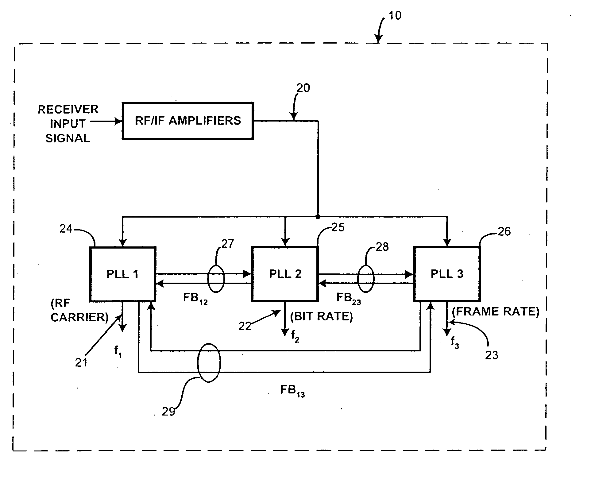
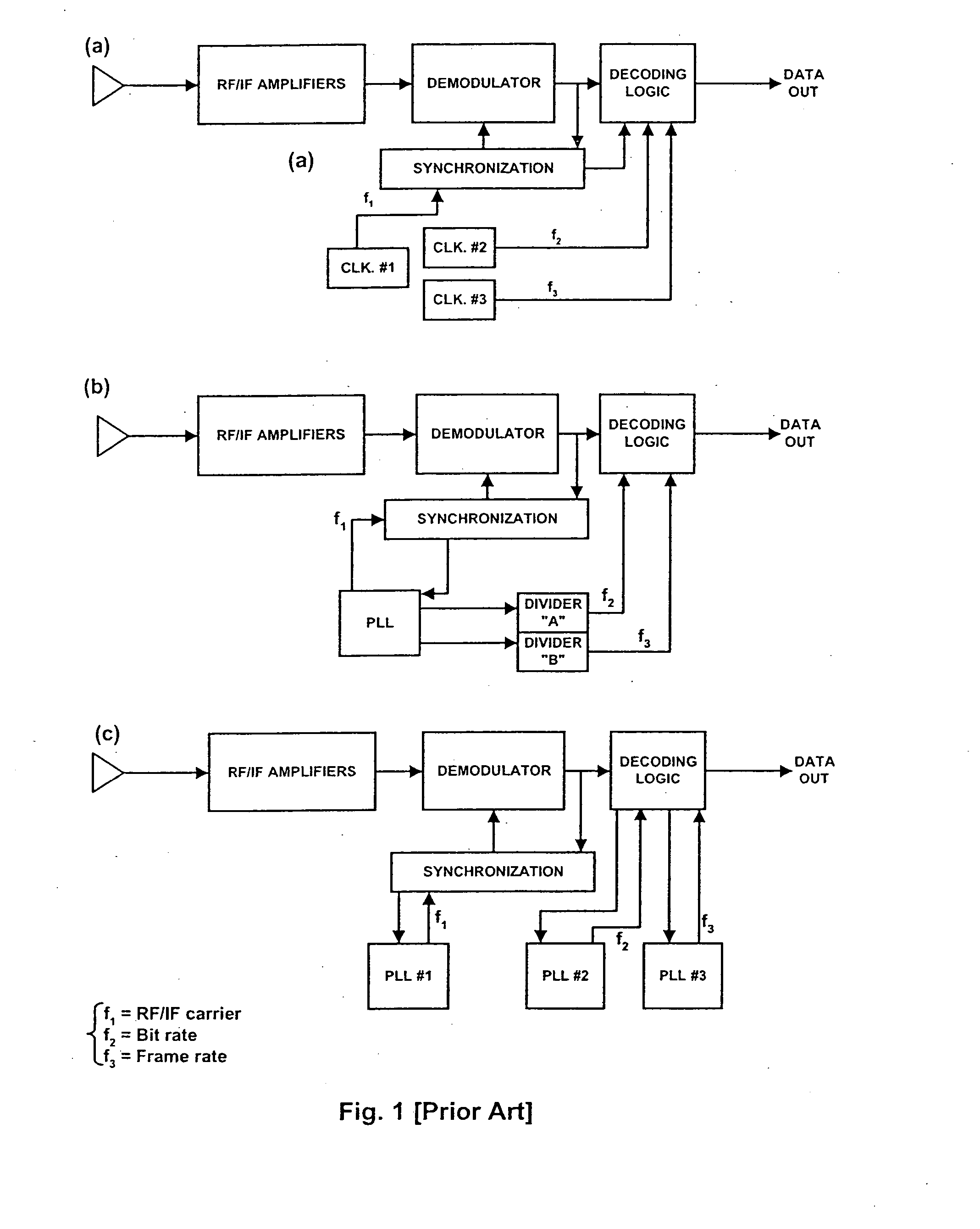
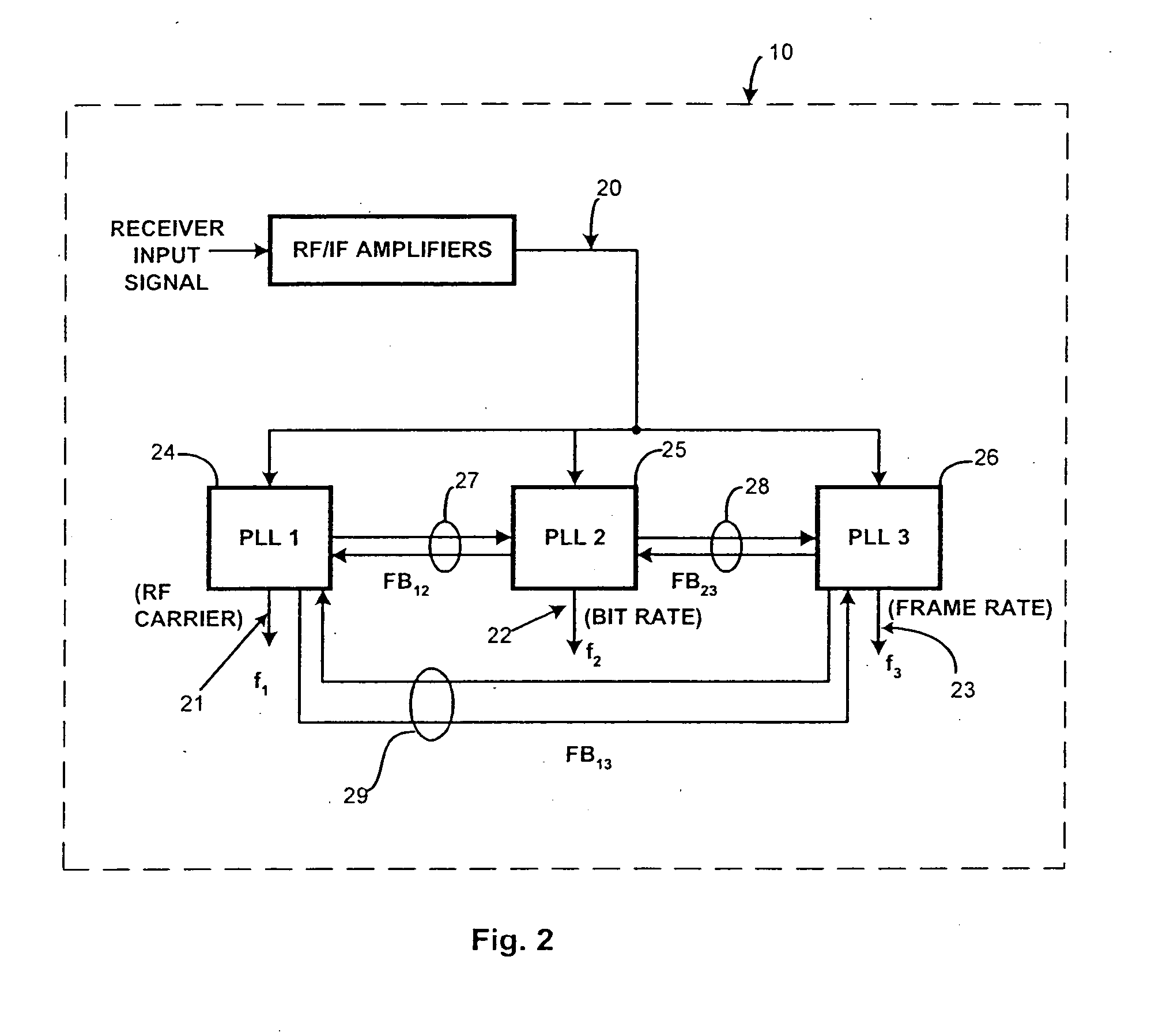
[0057] FIG. 1 of the drawings provides typical block diagrams of receiver synchronization architectures according to the current-art techniques. FIG. 1(a) shows a basic scheme with a multiple unrelated clocks; 1(b) illustrates a single master PLL / clock with downstream dividers to generate the secondary frequencies; and 1(c) details three independent PLLs (one per frequency). FIG. 2 of the drawings is a typical block diagram of the basic functioning of the receiving system 10 of the current invention. As shown in FIG. 2, the receiving system 10 is designed to detect three distinct timing signals or frequencies of an input signal 20, such as the RF carrier f.sub.1 21, the data bit (baud rate) f.sub.2 22, and the data frame rate f.sub.3 23. In many instances there will be a need for additional timing signals to be regenerated, including but not limited to the spread-spectrum chipping clock, transmission burst rate, epoch clocks, and othe...


PUM


Abstract

An improved digital-data receiver synchronization apparatus and method is provided wherein memory devices in the receiver such as phase-lock loops are provided with composite phase-frequency detectors, mutually cross-connected comparison feedback means, or both to provide robust reception of digital data signals. The apparatus and method are preferrably utilized with synchronous architecture wherein a single master clock is used to provide frequency signals to the memory devices, and also can be used with asynchronous architecture. The apparatus and method provide fast lock-up times in moderately to severely noisy conditions and have improved tolerances to clock asymmetries.

Description

[0002] The current invention relates generally to digital-data receivers, and particularly to an improved digital-data receiver using multiple cross-coupled synchronization loops.[0003] 1. Field of the Invention[0004] Most digital transmitter devices utilize separate frequency-reference sources (e.g., crystal oscillators, SAW resonators, etc.) to determine the various parameters of transmission such as RF carrier frequency, data-transmission bit (baud) rate, data-burst timing, and interface data rates (e.g., serial data input speeds). Even in frequency-synthesized units, one or more crystals are invariably used to set not only the carrier center frequencies, but also channel step sizes and the like. In digital systems incorporating data-acquisition functions, the required A / D converters are often run at independently selected rates dictated by the specific application. Additionally, in the typical modern system implementations employing embedded microprocessors or microcontrollers, ...

Claims


Application Information

Patent Timeline
IPC IPC(8): H03L7/07H03L7/087H03L7/089H03L7/191H03L7/23H04J3/06
CPCH03L7/07H03L7/087H04J3/0685H03L7/191H03L7/23H03L7/0891
Inventor SMITH, STEPHEN F.TURNER, GARY W.
Owner UT BATTELLE LLC
Why Eureka
Try Eureka