Method and apparatus for converting supplies and reducing waste

a technology of waste canisters and supplies, applied in the field of waste canister systems, can solve the problems of inconvenient use of large equipment, weight disadvantage of 5,000, 10,000 and 15,000 cubic centimeter containers, cross contamination in any system, etc., and achieve the effect of reducing the amount of material waste, reducing the internal distribution, and reducing was

Inactive Publication Date: 2004-06-24
MEDINDICA PAK
View PDF50 Cites 39 Cited by
  • Summary
  • Abstract
  • Description
  • Claims
  • Application Information

AI Technical Summary

Benefits of technology

0007] One object of the invention is to fabricate a delivery container for disposal and coupling to a waste collection system. Another objective of the invention is to provide a delivery and collection container system using bottles fabricated from a blow molding process. Another object of the invention is to provide a delivery and collection container fabricated from a blow fill seal manufacturing process. Another object of the invention is to provide a suction / vacuum system which renders product distribution / transfer containers receptive to waste materials. Another object of the invention is to provide a collection system for reducing waste that is derived from a product delivery. Still a further purpose of the invention is to provide container options for reducing the amount of material waste introduced to the waste stream in the medical field. Another object of the invention is to deposit waste materials into a container derived from the product transfer distribution / commercializatio-n cycle and converted into a waste receptacle. Another object of the invention is to use intravenous solution containers as converted receptacles for waste materials. Another object of the invention is to use pour bottles and convert them as receptacles for waste materials. Another object of the invention is to fabricate a waste reducing system which conveys waste reduction options. Another purpose of the invention is to reduce the internal distribution, the inventory management of surgical waste collection devices. Another purpose of the invention is to provide methods and apparatus effecting the utility of reducing handling associated with the collection of surgical material waste. A further purpose of the invention is to provide methods and apparatus to reduce re-cycling, re-processing, and re-use procedures. Still a further object of the invention is to fabricate systems which utilize the cubic space capacity embodied in product distribution, delivery and transfer containers such as pour bottles and intravenous solution containers for waste collection and disposal. Yet another object of the invention is to provide methods and apparatus for the consumer to account for cubic volumes of incoming fluids and cubic volumes of outgoing waste materials for cost effectiveness and better supply planning and purchasing. And still a further object of the invention is to provide methods and apparatus in a system that provides cost effective container conversion and transformation procedure, supply planning, ordering, inventory carrying, procedure supply selection and supply utility. Yet another object of the invention is to provide more cost effective means for collecting surgical waste materials. Still a further object of the invention is to interpose the inner chamber of a plastic pour bottle along an draw path at a location between a material waste source (surgical site) and a source from which the draw force emanates. Still a further object of the invention is to provide a suction collection system fabricated to connect to a pour bottle. Still a further object of the invention is to provide a suction / vacuum system to connect to an intravenous solution container. Still a further object of the invention is to fabricate a blow molded bottle to fit to a suction canister system by a bayonet movement. Still a further object of the invention is to provide a blow molded container comprising a neck structuration for coupling to a lid / cover boss. Still a further object of the invention is to integrate the inside of a distribution / commercialization product transfer container into the vacuum / suction draw control path for reception of waste materials. Still a further object of the invention is to reinforce the walls of a product distribution / commercialization using a vacuum / suction force. Still a further object of the invention is to interpose a transfer container along an intermediate portion of a draw control path between a vacuum / suction source and a source of waste material. Still a further object of the invention is deposit waste materials into a product distribution / commercialization transfer container by a draw force. Still a further object of the invention is to couple a canister cover to a product distribution / transfer container. Still a further object of the invention is to fabricate a product transfer container to couple to a canister cover. Still a further object of the invention is to fabricate a container and a canister cover to couple together. Yet another object of the invention is to provide for container Techni-cycling (as defined above)

Problems solved by technology

A container of this size has disadvantages because it is too big for many collection applications.
Larger equipment is also inconvenient in smaller rooms, where suction collection equipment is found such as the emergency room, intensive care units in patient hospital rooms, coronary care units, and neo-natal and infant care units, physician offices, physician owned surgery suites, out patient surgery centers, ambulances, and other rooms defining smaller confined spaces.
There are also concerns with cross contamination in any system where contaminated waste material remains in a room / location during the presence of multiple patients.
This problem is most prevalent in intensive care and other patient units where the most sick patients are treated.
Another disadvantage of 5,000, 10,000 and 15,000 cubic centimeter containers is weight.
Such weight in these very heavy volumes provide for extremely difficult ergonomics and handling problems posing significant risk to personnel, such as back, neck, and upper extremity injuries.
Another disadvantage of such large and heavy containers is its size.
Such large containers are more difficult to clean and cumbersome to handle and because the awkward size, could contribute to such problems as carpal tunnel syndrome of the wrist, which further defines ergonomic problems with respect to the disadvantages of such heavy fluid products as related to the U.S. Pat. No. 5,792,126 reference.
This renders this invention a disposable product which is costly whereby each time a canister is used, another purchase is made by the customer, and another product enters internal distribution increasing cost cycles and increasing inventory handling costs and another piece of garbage enters the waste stream which is a serious disadvantage.
This makes the system expensive, and requires ongoing internal distribution, requiring ongoing inventory space, which is at a premium in most institutions.
Another disadvantage is the lack of choice for the customer to re-process, re-sterilize, or re-use, of which options are beneficial, but not available with the U.S. Pat. No. 5,960,837 reference.
This system comprises complex equipment for handling a collection canister.
The disadvantages to this system are expensive equipment is required, and such complex equipment needs expensive maintenance plus required periodic inspection which increases labor costs associated with its presence.
In addition, the equipment must be kept clean, which is additional labor required for daily operations.
Other disadvantages include a re-usable canister which requires costly labor for internal processing, re-processing and re-using.
In most institutions volume of such collection systems is quite high imposing expensive internal handling and re-use processing costs.
The system discloses a disposable flush kit which maintains higher disposable costs along with higher costs associated with internal distribution and inventory handling.
This requires additional labor, which is costly, and involves the inventory and tracking of a plurality of systems in sets.
Often times lids and liners can become separated and when out of numerical matching balance, one cannot be used without the other whereas resulting in an incomplete set and an unusable sub-assembly.
This disadvantage complicates the ongoing internal distribution and tracking of the subassembly components, which adds costly labor, inventory management and excess handling.

Method used


Image

  • Method and apparatus for converting supplies and reducing waste
  • Method and apparatus for converting supplies and reducing waste
  • Method and apparatus for converting supplies and reducing waste

Examples


embodiment 1

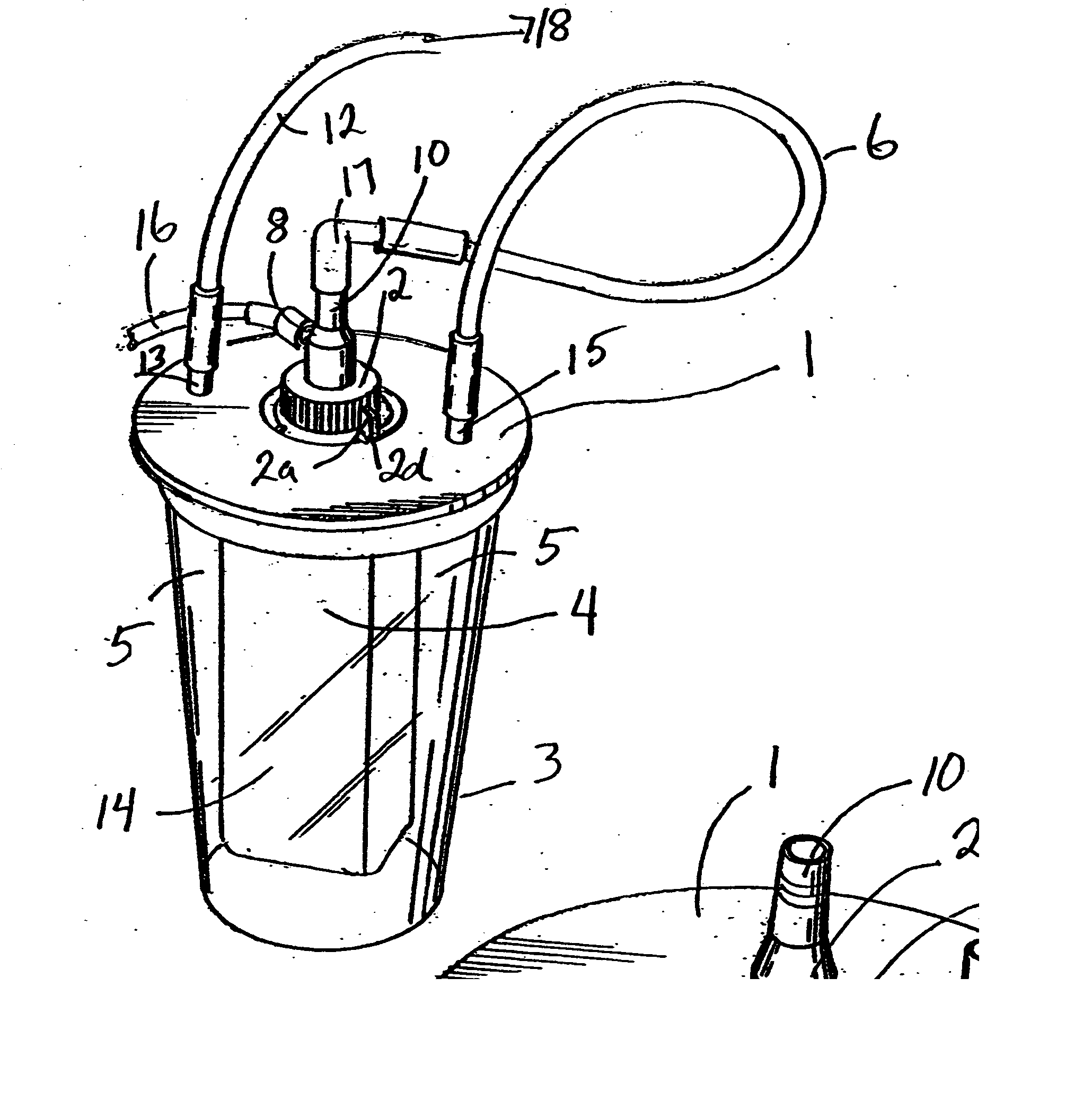
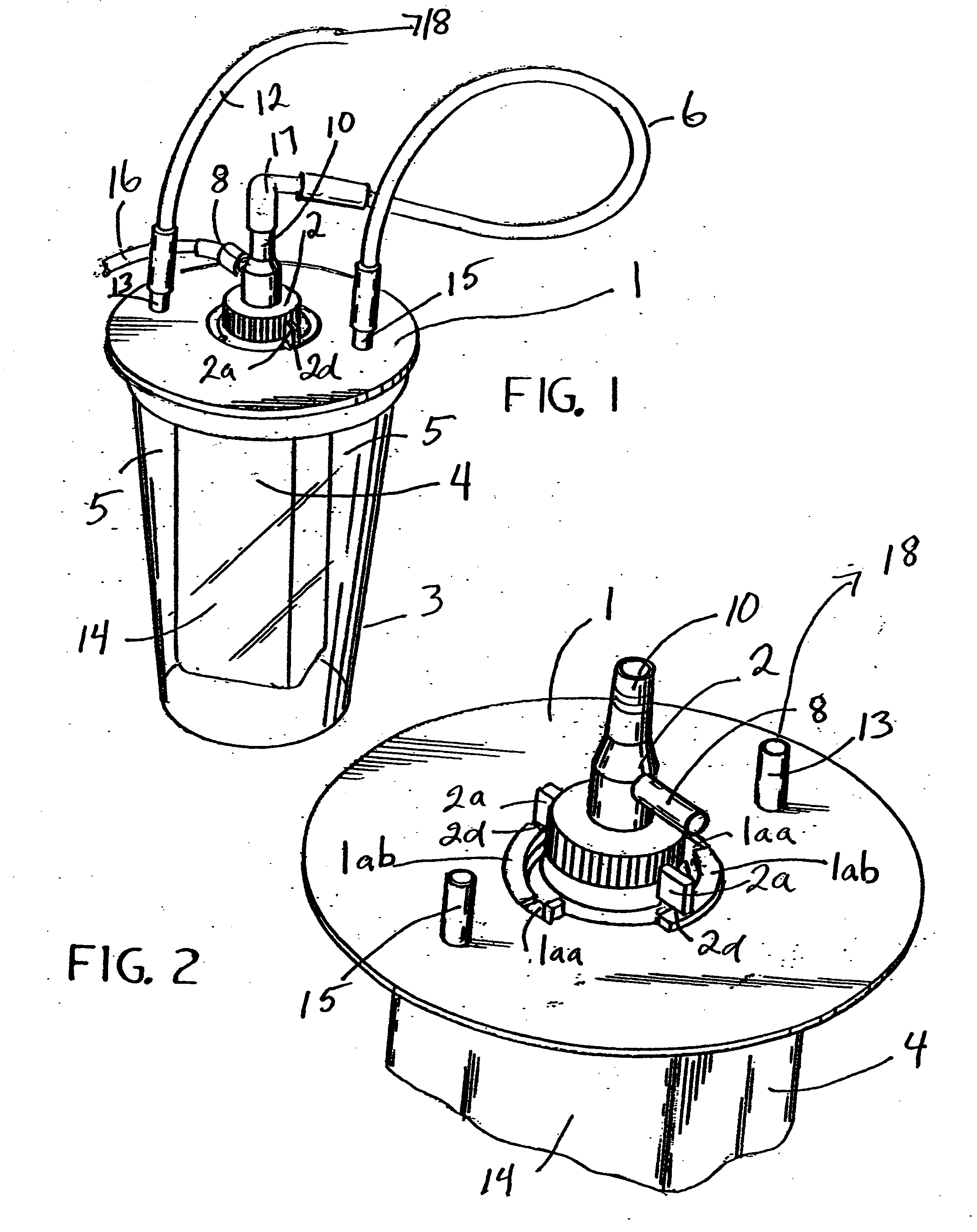
[0009] FIG. 2 is a partial top perspective of a pour bottle coupled to a bottle cap and connected to canister lid

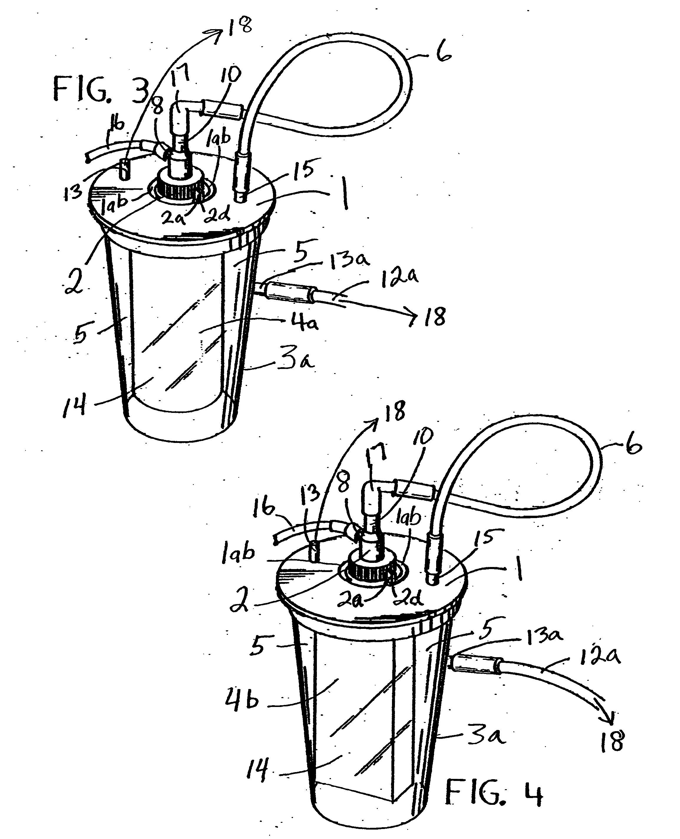
[0010] FIG. 3 is a top perspective view of a plastic pour bottle disposed within a surgical suction / vacuum canister system that has a side vacuum draw port.

[0011] FIG. 4 is a top perspective view of a plastic pour bottle disposed within a surgical suction / vacuum canister system as a receptacle for the collection of surgical material waste deposits and the suction canister housing body has a side vacuum / suction draw port.

[0012] FIG. 5 is a partial side elevational view of a plastic pour bottle and neck.

[0013] FIG. 6 is an exploded side elevational view of a plastic pour bottle, a bottle vacuum pressure exchange cap and a partial side elevation view of lid embodiment 1.

[0014] FIG. 7 is a partial cross section view of a plastic pour bottle disposed as a receptacle for receiving deposits of surgical material waste connected to a vacuum transfer cap which is in turn connected ...

embodiment 2

[0024] FIG. 14 is a partial side elevation of a surgical suction canister lid embodiment 2 connected to a plastic pour bottle disposed therewith as a receptacle for collecting surgical suction material waste deposits through throat / aperture vacuum exchange plug 7.

[0025] FIG. 15 is a partial cross sectional view of a portion of a plastic pour bottle neck interposed between a throat / aperture plug and a surgical suction canister lid embodiment 2 and disposed therewith as a receptacle for surgical suction waste material via means of throat / aperture plug 7.

[0026] FIG. 16 is a partial cross section of surgical suction canister lid base 1a1 for adaptability to several sizes of suction canister body / housings.

[0027] FIG. 17 is a cross section view of throat / aperture force exchange plug 7.

[0028] FIG. 17a is a partial cross section view of surgical canister lid embodiment 2 coupled to the outer contour of a plastic pour bottle neck having the bottle disposed therewith to receive throat apertur...

second embodiment

[0071] Turning to FIG. 21. FIG. 21 shows material composite conduits of FIG. 19 and FIG. 20 as attached to in-draw connector 9 of a second embodiment throat / aperture plug 7a. It is also understood that the in-draw conduit composite of suction tip 19, suction tubing 16 and connector 9 may be permanently joined, or previously releasably connected as an integral material in-draw conduit.

[0072] Turning to FIG. 22. FIG. 22 shows a third embodiment throat / aperture plug 7b with out draw line filter 35, out-draw connector 11, outline filter space 36, in-draw connector 9, suction tubing connection 16 and material deposit spout 9a. It is understood that these components may be permanently connected to third throat / aperture embodiment 7b or they may be releasable connectable to throat / aperture embodiment 7b.


PUM

PropertyMeasurementUnit
pressuresaaaaaaaaaa
thickaaaaaaaaaa
forceaaaaaaaaaa

Abstract

A method and apparatus for technique and cycling (Techni-cycling as herein defined) such that converting delivery supply containers (supplies) into waste and disposal receptacles is disclosed. More particularly, a container transformation comprising deriving a supply container from a health care delivery sequence and converting the container into a waste receptacle by connection to a vacuum/suction source and collection system reduces the amount of waste contributed to the waste stream.

Description

[0001] This application claims the benefit, under 35 U.S.C. 119(e) of U.S. Provisional Patent Application Serial No. 60 / 432,517, filed Dec. 11, 2002.[0002] This invention(s) relates to the field of reducing the waste stream burden in the medical field.[0003] In particular, this application relates to systems used for the collection and disposal of certain medical waste. The collection of fluent waste material is a common procedure in the medical field. Most methods of surgical waste collection are carried out using vacuum suction. Some methods use gravity, while some use impelling devices which produce suction / vacuum. Examples of such impelling devices may comprise a meniscus shaver, a lipo-suction system, an arthroscopic fluid pump, an endoscopic irrigation and aspiration wand and the like. Surgical fluid waste is collected in containers commonly referred to as canisters, and or canister liners. These waste collection devices are generally disposable, some are recycled reprocessed ...

Claims


Application Information

Patent Timeline
Patent Type & Authority Applications(United States)
IPC IPC(8): A61M1/00B65D
CPCA61M1/0001A61M1/60
Inventor ROMANO, JACK W.SMITH, ADAM L.
Owner MEDINDICA PAK
Why Eureka
Try Eureka