Method and device for generating extreme ultravilolet radiation in particular for lithography

a technology of ultravilolet radiation and generator, which is applied in the direction of radiation therapy, x-ray tube gas filling, and x-ray tube with very high current, etc., can solve the problems of large number of atoms, erosion of the nozzle, and significant material debris, and achieves high reliability and great simplicity

Inactive Publication Date: 2004-07-08
COMMISSARIAT A LENERGIE ATOMIQUE ET AUX ENERGIES ALTERNATIVES
View PDF11 Cites 42 Cited by
  • Summary
  • Abstract
  • Description
  • Claims
  • Application Information

AI Technical Summary

Benefits of technology

0043] More generally, the present invention relates to a method and a device for generating a dense fog of droplets from a liquid, whereby this method and this device may be used for producing EUV radiation and also have high reliability as well as great simplicity which is essential for industrial use.

Problems solved by technology

Further, the local density of the atoms in each cluster is relatively high, so that a large number of atoms are involved.
On the other hand, significant material debris may result from the erosion of the nozzle when the latter is placed too close to the area illuminated by the laser.
In addition, the closeness of the illuminated area and of the nozzle may cause heating of the latter with deterioration of the jet's characteristics.
This is why excitation from the laser beam should take place in the direct vicinity of the nozzle, which causes significant erosion of this nozzle by the impact of ions from the generated plasma or by an electric discharge.
The nozzle's erosion significantly reduces its lifetime, and therefore the reliability of the EUV radiation source, and generates large amounts of debris, capable of untimely deteriorating the optics of a lithographic apparatus using such a source.
Poor directivity of the xenon cluster jet induces a EUV radiation re-absorption phenomenon by the cluster jet itself, the interaction with the laser taking place at the center of the cluster jet, which substantially reduces the intensity of the actually usable EUV radiation.
Such microcrystals are too large for the penetration of the excitation laser beam to be complete.
The technique described in document [4] therefore does not meet the criteria for obtaining a sufficiently intense EUV radiation source.
This kind of target also has the drawback of containing a far too small amount of material in order to obtain a sufficient number of potential EUV emitters.
Furthermore, the sources known from documents [4] and [5] are not very stable as regards intensity.
In the case of document [4], it is difficult to irradiate each ice microcrystal in the same way because of a synchronization problem with the laser.

Method used


Image

  • Method and device for generating extreme ultravilolet radiation in particular for lithography
  • Method and device for generating extreme ultravilolet radiation in particular for lithography
  • Method and device for generating extreme ultravilolet radiation in particular for lithography

Examples


Embodiment Construction

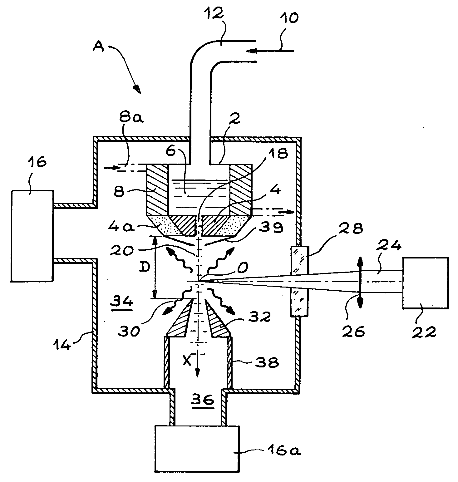
[0086] The device A for generating a fog according to the invention, which is schematically illustrated in FIG. 1, comprises a tank 2 and a nozzle 4. This nozzle 4 is positioned close to the tank 2 and communicates with the latter.

[0087] This tank 2 is for containing liquid xenon 6. Cryogenic means 8 are provided for producing this liquid xenon 6 from xenon gas 10.

[0088] Furthermore, the liquid xenon 6 is pressurized by this xenon gas 10. The latter is injected into the tank 2 via a duct 12 and liquefied by the cryogenic means 8 in order to form liquid xenon.

[0089] As an example, these cryogenic means comprise a tube 8a which clasps the tank and the nozzle, only portions of this tube are illustrated in dot and dash lines in FIG. 1, and a cryogenic fluid, for example nitrogen, runs through this tube.

[0090] In addition, these cryogenic means 8 comprise control means (not shown) capable of maintaining liquid xenon at a set temperature T, with -70.degree. C..ltoreq.T.ltoreq.-20.degree. ...


PUM

PropertyMeasurementUnit
sizeaaaaaaaaaa
sizeaaaaaaaaaa
pressureaaaaaaaaaa

Abstract

Method and device for generating light in the extreme ultraviolet, notably for lithography. According to the invention, a laser beam (24) is caused to interact with a dense fog (20) of microdroplets of a liquid. This liquid is a liquefied noble gas. In particular, liquid xenon (6) is used, the latter is produced by liquefying gaseous xenon (10) with which liquid xenon is pressurized to a pressure from 5x10<5 >Pa to 50x10<5 >Pa, and this liquid xenon is maintained at a temperature from -70° C. to -20° C., the pressurized liquid xenon is injected into a nozzle (4) the minimum internal diameter of which ranges from 60 mum to 600 mum, this nozzle opening into an area where pressure is equal to or less than 10<-1 >Pa.

Description

[0001] The present invention relates to a method and a device for generating light in the extreme ultraviolet region, notably for lithography by means of such a light.[0002] The increase in the power of integrated circuits and the integration of more and more functions into a small space require a great technological jump in the lithographic technique, used traditionally for manufacturing integrated circuits.[0003] The microelectronics industry notably provides the use of radiation from the extreme ultraviolet (EUV) region for insolating photosensitive resins in order to achieve critical dimensions less than or equal to 50 nanometers on silicon.[0004] In order to produce this radiation, for which the wavelength lies between 10 nm and 15 nm, a large number of techniques have already been suggested. In particular, irradiation of a target, by focussed laser radiation seems to be the most promising technique for achieving good performances in the mean term both in terms of average power...

Claims


Application Information

Patent Timeline
Patent Type & Authority Applications(United States)
IPC IPC(8): G03F7/20H01J35/20H05G1/00H01L21/027H05G2/00
CPCG03F7/70033H05G2/006H05G2/008H05G2/003H05G2/00
Inventor SCHMIDT, MARTINSUBLEMONTIER, OLIVIERCECCOTTI, TIBERIOSEGERS, MARC
Owner COMMISSARIAT A LENERGIE ATOMIQUE ET AUX ENERGIES ALTERNATIVES
Why Eureka
Try Eureka