
Rolling-bearing and bearing unit

a technology of rolling bearings and bearings, which is applied in the direction of rotary machine parts, mechanical equipment, chemistry apparatus and processes, etc., can solve the problems of difficult to reduce contamination any further using just this method, difficult to remove very small burrs from machined surfaces, and difficult to remove remaining abrasives, especially sticked thorn-like abrasives

Inactive Publication Date: 2004-07-08
NSK LTD
View PDF8 Cites 3 Cited by
  • Summary
  • Abstract
  • Description
  • Claims
  • Application Information

AI Technical Summary

Benefits of technology

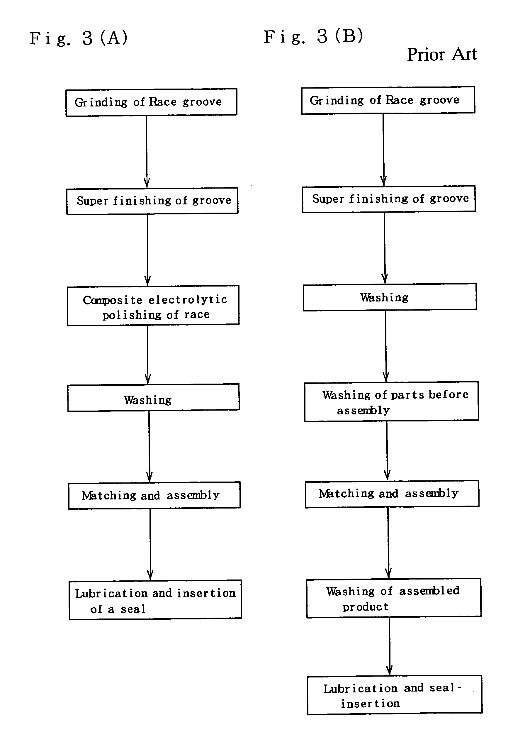
The invention relates to a rolling bearing with a surface layer that is formed on at least one of the raceways of the races by machining and electrochemical or chemical dissolution of the machined surface. This surface layer reduces contamination and improves resistance to wear and damage. The invention also includes a method of manufacturing the rolling bearing by grinding and super-finishing the raceway surface, then forming the surface layer by electrochemical or chemical dissolution of the machined surface, and washing the races before assembly. The invention is useful in fields such as information-processing devices and aerospace devices where high resistance to wear and low generation of dust particles are desired.

Problems solved by technology

Conventionally, it has been possible to reduce contamination by washing in the assembly process after surface finishing, however, it is difficult to reduce contamination any further using just this method.
Toku Kai Sho 62-24956, finishing is performed by machining, so it is difficult to remove very small burrs from the machined surfaces, and it is difficult to remove remaining abrasive, particularly sticked thorn-like abrasive.
Further, it is difficult to remove minute burrs even by performing supersonic washing for a long period of time.
Toku Kai Hei 3-84218 is effective in removing large burrs and sludge, however, since finishing is performed by machining, it is difficult to remove remaining abrasive, particularly sticked thorn-like abrasive.
Also, with the technology of this same publication, it is not possible to form a surface layer over the entire races by electrochemically or chemically dissolving the machined surfaces of the races.
However, during this time, wear occurs to the raceway surfaces and the rolling surfaces.
Even for small amounts of wear, that wear spreads and contamination occurs after long periods of operation in the special environment of space, making it difficult to maintain the function of the rolling bearing.

Method used


Image

  • Rolling-bearing and bearing unit
  • Rolling-bearing and bearing unit
  • Rolling-bearing and bearing unit

Examples


Embodiment Construction

[0039] A bearing outer race made of SUS440C was prepared and composite electrolytic polishing was performed for it. After a suitable amount of particles were made to adhere to the surface, the outer race was washed. Washing was performed by immersing the outer race in a clean solution and then irradiating it with supersonic waves. After each specified interval of supersonic irradiation, the particles having a size of 1 .mu.m or greater and that were released into the solution were counted by a particle counter in the solution. The surface roughness Rmax of the outer race for which the composite electrolytic polishing process was performed was 0.3 .mu.m for the inner-diameter surface and outer-diameter surface, and 0.27 .mu.m for the end surfaces.

[0040] As a comparison, a bearing outer race made of SUS440C was prepared without composite electrolytic polishing performed for it. After a suitable amount of particles were made to adhere to the surface, the outer race was washed and the p...


PUM


Abstract

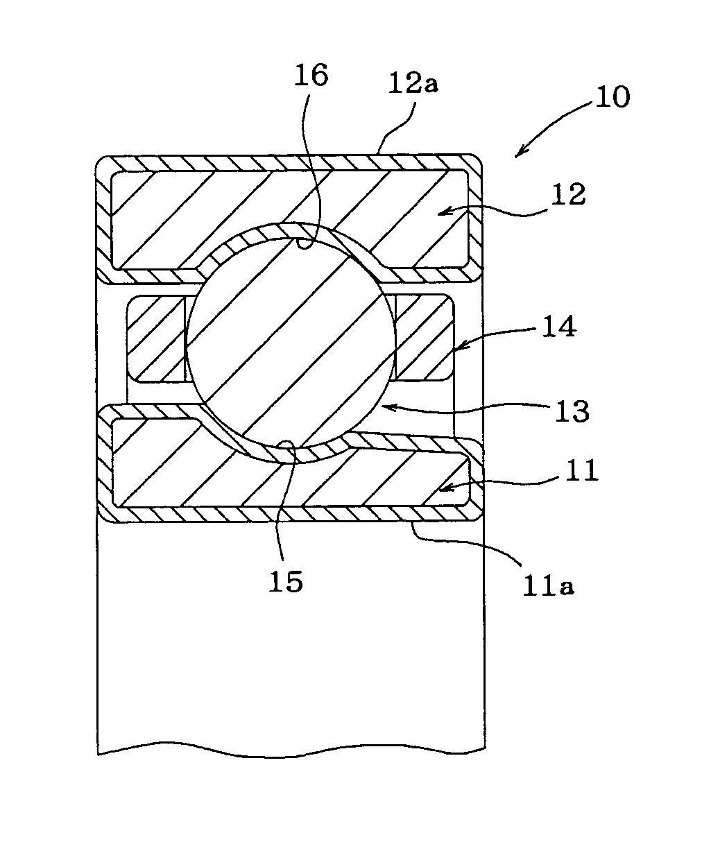
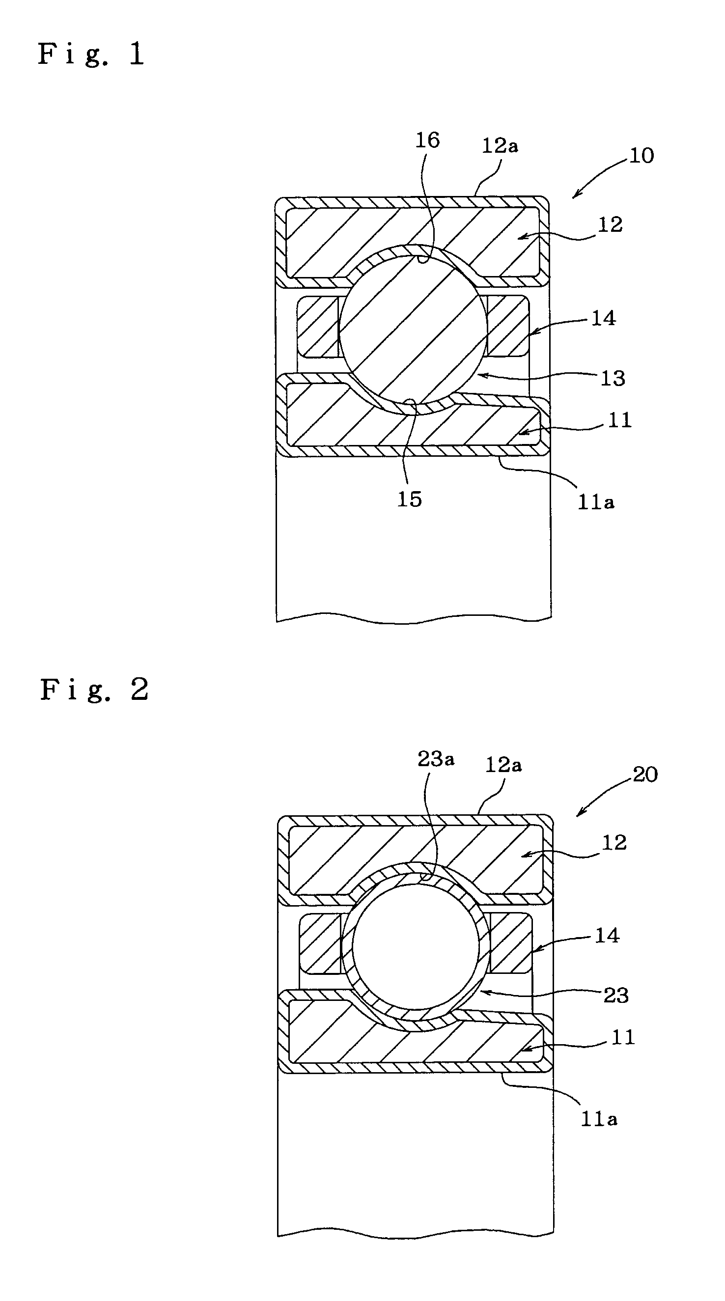
A rolling bearing 10 comprises races 11, 12 having a raceway 15, 16 and rolling elements 13 having a rolling contact surface, wherein at least the raceway 15, 16 of the races 11, 12 has a machined surface, and a surface layer 11a, 12a is formed on the machined surface by electrochemically or chemically dissolving the machined surface, whereby contamination is substantially reduced.

Description

[0001] This is a continuation of pending U.S. application Ser. No. 10 / 029,419 filed Dec. 20, 2001.[0002] This invention relates to a rolling-bearing and a bearing unit that are used in fields such as information-processing equipment, aerospace, airplane and semiconductors.DESCRIPTION OF THE RELATED ART[0003] In order to improve resistance to wear, and reduce the generation of dust particles of a rolling bearing, the following methods have been proposed as methods for surface finishing of the raceway surfaces.[0004] Japanese patent publication No. Toku Kai Sho 62-24956 proposes a method of using lapping tape coated with cubic boron nitride (CBN) abrasive grain to lap the raceway groove (raceway surface).[0005] Japanese patent publication No. Toku Kai Hei 3-84218 proposes a method of finish-grinding the circumferential seal groove of the races simultaneously when finish-grinding the inner-raceway surface and outer-raceway surface, using the same grinding abrasive.[0006] Recently, roll...

Claims


Application Information

Patent Timeline
Patent Type & Authority Applications(United States)
IPC IPC(8): F16C33/32F16C33/58F16C33/62B64G1/28F16C33/64
CPCF16C33/62Y10S451/901F16C33/64F16C2235/00
Inventor MATSUZAKI, HIROYUKI
Owner NSK LTD
Learn More