

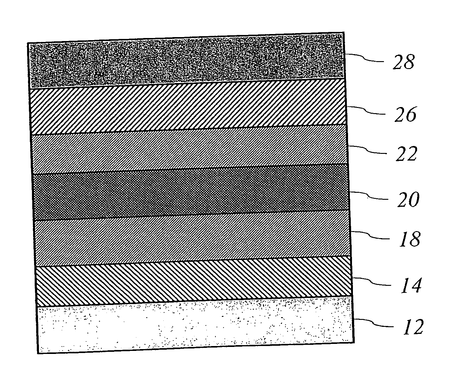
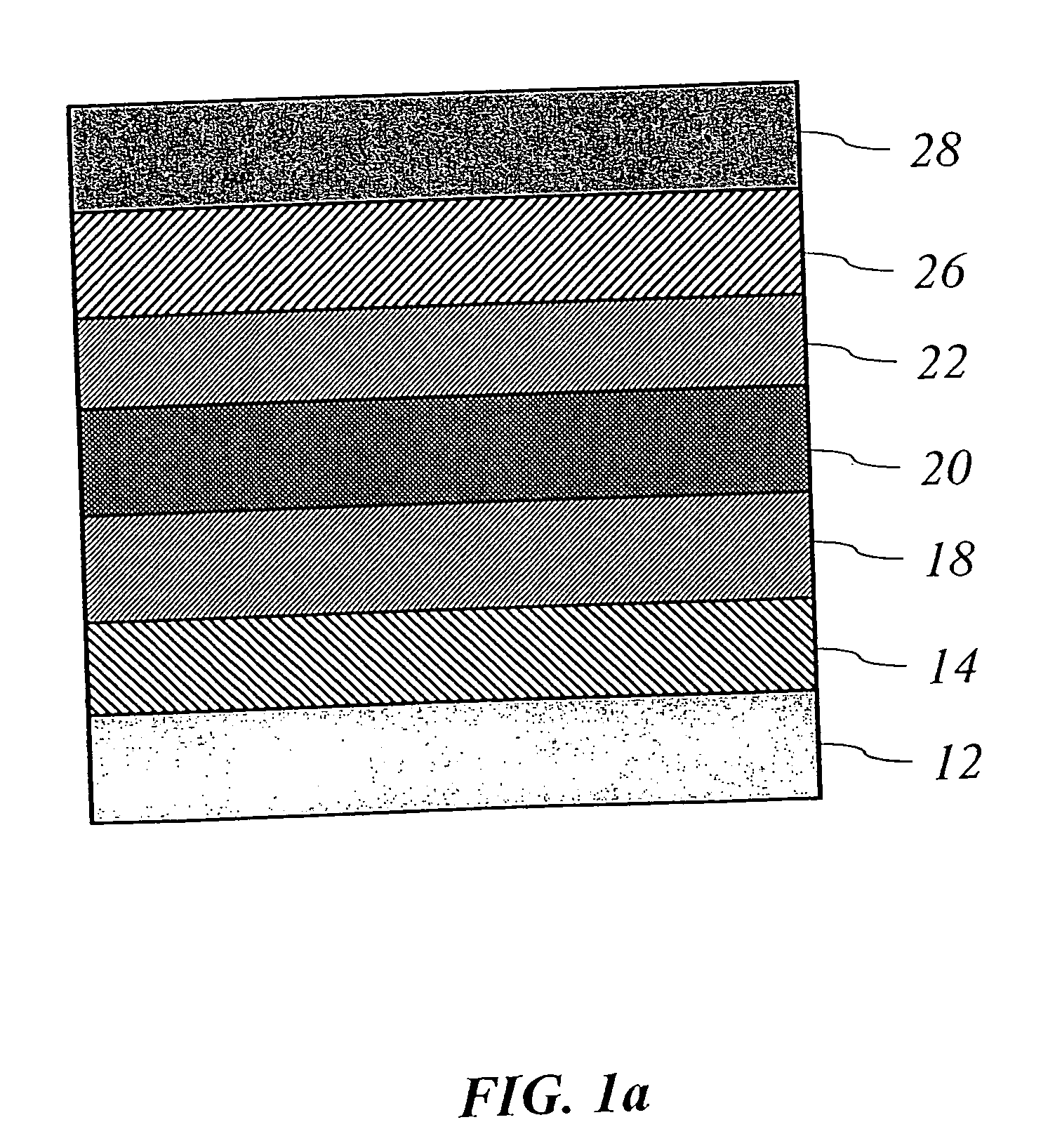
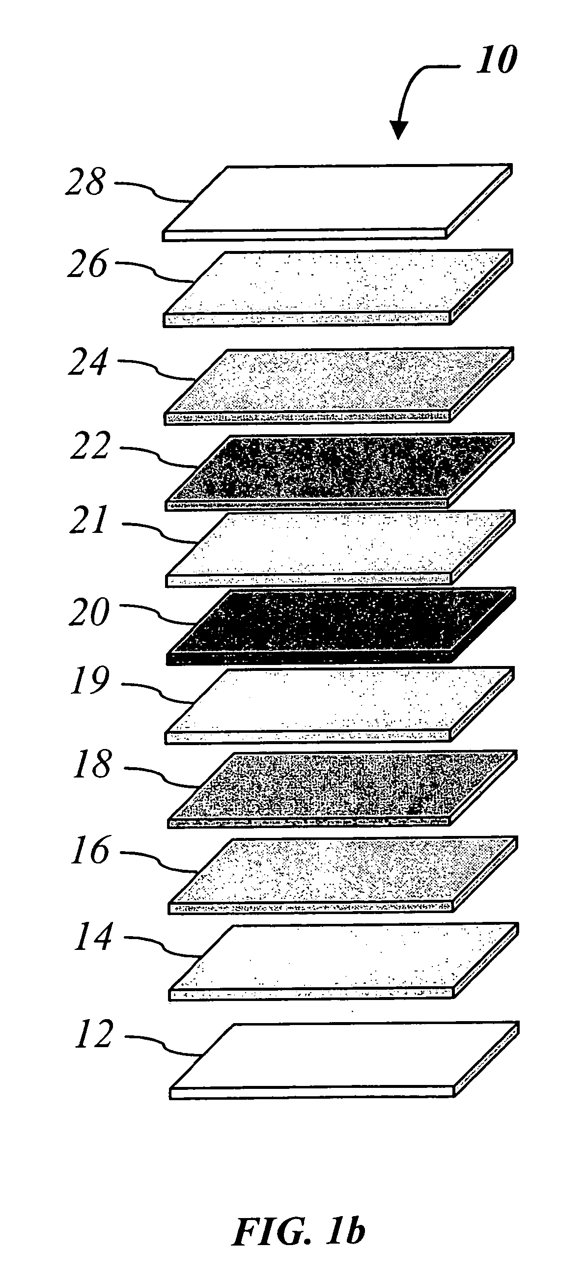
Method and system for fabricating an OLED
a technology of oled and olefin, which is applied in the direction of vacuum evaporation coating, solid-state devices, coatings, etc., can solve the problems of not universal and versatile in general, difficult or impossible to employ the same technique for polymers with a much higher molecular weight, and difficult to achieve the effect of achieving uniform thickness and uniform thickness
- Summary
- Abstract
- Description
- Claims
- Application Information
AI Technical Summary
Problems solved by technology
Method used
Image

Examples
example 1
[0105] A pellet made of an organic chelate, 2,6-Pyridine dicarboxylic acid europium dimethylamine complex 3:1:3 (Eu(DPA).sub.3(NH.sub.2Me.sub.2).sub-.3), was placed into a vacuum chamber as illustrated in FIG. 2. In this example, only a double beam alexandrite laser 114a referred to as Pulse Laser #1 was used. A laser beam 116 having a single-mode wavelength of 760 nm was redirected using mirror 115 and semitransparent mirrors 115a and 115b upon the surface of a pellet 118 forming a spot of about 1 mm in diameter to deliver energy of 80 mJ at a pulse repetition rate of 10 Hz. Deposition for 25 minutes onto a glass substrate resulted in a substantially uniform film having a thickness of 1400 .ANG..
example 2
[0106] Similarly to Example 1, a pellet was made of an organic chelate, Eu(DPA).sub.3(NH.sub.2Me.sub.2).sub.3, and placed into a vacuum chamber as illustrated in FIG. 2a. Again, only a double beam alexandrite laser 114a referred to as Pulse Laser #1 was used. A laser beam 116 having a wavelength of 760 nm was redirected using mirror 115 and semitransparent mirrors 115a and 115b and through focusing lens 113 upon the surface of a pellet 118 forming a spot of about 1 mm in diameter to deliver energy of 120 mJ at a pulse repetition rate of 10 Hz. Deposition for 25 minutes onto a glass substrate resulted in a substantially uniform film having a thickness of 1800 .ANG..
example 3
[0107] Similarly to Example 2, a pellet was made of an organic chelate, Eu(DPA).sub.3(NH.sub.2Me.sub.2).sub.3, and placed into a vacuum chamber as illustrated in FIG. 2. Two lasers 114a and 114c referred to as Pulse Lasers #1 and and #3 were simultaneously turned on. A laser beam having combined radiation wavelengths of 380 nm and 760 nm from a double beam alexandrite laser 114a operating at a pulse repetition rate of 10 Hz was redirected using mirror 115 and semitransparent mirrors 115a and 115b upon the surface of a pellet forming a spot of about 1 mm in diameter to deliver energy of 20 mJ at 380 nm and 120 mJ at 760 nm. A second laser beam having a frequency of 308 nm from the XeCl excimer laser 114c delivered energy of 100 mJ at a pulse repetition rate of 10 Hz through semitransparent mirror 115b. All laser beams were mixed and focused by focusing lens 113. Deposition for 20 minutes onto a glass substrate resulted in a substantially uniform film having a thickness of 1100 .ANG.....
PUM
| Property | Measurement | Unit |
|---|---|---|
| Temperature | aaaaa | aaaaa |
| Thickness | aaaaa | aaaaa |
| Angle | aaaaa | aaaaa |
Abstract
Description
Claims
Application Information