Conductive catalyst particle and its manufacturing method, gas-diffusing catalyst electrode, and electrochemical device

a technology of catalyst electrode and catalyst particle, which is applied in the direction of catalyst activation/preparation, metal/metal-oxide/metal-hydroxide catalyst, etc., can solve the problem that the adhesion does not give the alloy, and achieve good catalytic activity and avoid internal self-diffusion

Inactive Publication Date: 2004-07-22
SONY CORP
View PDF6 Cites 41 Cited by
  • Summary
  • Abstract
  • Description
  • Claims
  • Application Information

AI Technical Summary

Benefits of technology

[0019] In order to address the problem, the present inventors carried out a series of researches, which led to the finding that preventing the catalytic material from suffering sintering requires that the catalytic material should not experience self-diffusion in its crystal lattice. Their researches also led to the finding that the internal self-diffusion can be avoided if an insoluble substance (which, even when heated, does not form alloy with a noble metal by solid solution) is compulsorily introduced into the crystal lattice of a noble metal, and the resulting product can be used as the catalytic material which is free of sintering. Their researches also led to the finding that the crystal grains of the catalytic material can be made fine if a solid-insoluble substance is compulsorily introduced into the crystal lattice of a noble metal as the catalytic material. The catalytic material containing such a solid-insoluble substance is inhibited from crystal growth, and hence it exhibits a good catalytic activity. The present invention is based on these findings.

Problems solved by technology

Incidentally, the conventional chemical process for adhesion does not give the alloy because it cannot introduce the solid-insoluble additive material into the noble metal.

Method used


Image

  • Conductive catalyst particle and its manufacturing method, gas-diffusing catalyst electrode, and electrochemical device
  • Conductive catalyst particle and its manufacturing method, gas-diffusing catalyst electrode, and electrochemical device
  • Conductive catalyst particle and its manufacturing method, gas-diffusing catalyst electrode, and electrochemical device

Examples


example 1

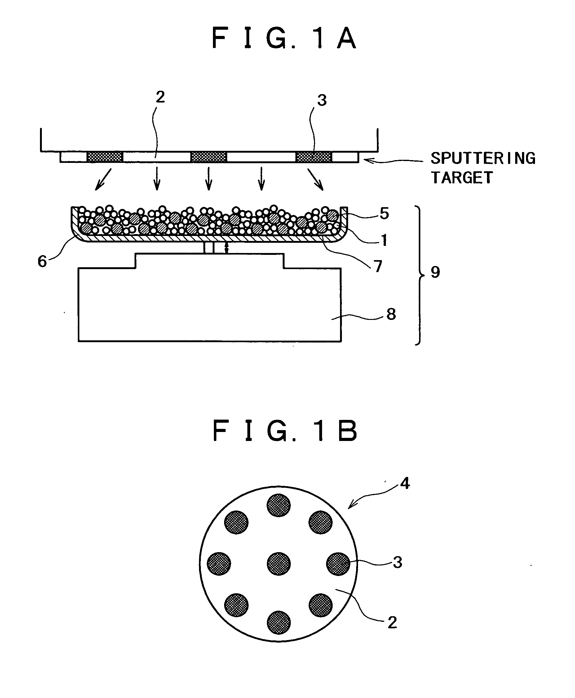
[0144] An apparatus shown in FIG. 1 was assembled from a sputtering target, a vibrator, and a container. The container was charged with a conductive powder and balls. The sputtering target (shown in FIG. 1B) is a platinum disk 100 mm in diameter, which is incorporated with boron (B) in such an amount that the film formed by sputtering contains as much boron as shown in Table 1 giver below. The balls are stainless steel balls 3 mm in diameter. The conductive powder is a carbon powder having a surface area of 800 m.sup.2 / g and an oil absorption value of 360 mL / 100 g. Sputtering is conducted with the vibrator generating vibration with an amplitude of 1 mm and a frequency of 36 Hz.

[0145] The container was charged with the carbon powder (1 g) and the stainless steel balls (35 g). Sputtering was carried out for 30 minutes while the carbon powder and stainless steel balls were being vibrated by the vibrator, with the vacuum chamber supplied with argon (at 1 Pa) and the target activated by ...

example 2

[0151] The same procedure as in Example 1 was repeated to prepare a fuel cell as shown in FIG. 10, except that B was replaced by SiO.sub.2 and the amount of SiO.sub.2 was varied as shown in Table 2. The resulting fuel cells were tested for initial output and output after operation for 200 hours. The results are shown in Table 2 and FIG. 15. Incidentally, the initial output (in terms of mW / cm.sup.2) generated by the fuel cell which employs the gas-diffusing catalytic electrode containing no SiO.sub.2 is regarded as the standard (100%) for relative values.

2TABLE 2 Output after Element operation for 200 added Amount added (mol %) Initial output (%) hours (%) SiO.sub.2 0 100 75 SiO.sub.2 1 100 82 SiO.sub.2 1.5 100 85 SiO.sub.2 2.0 107 100 SiO.sub.2 2.5 109 107 SiO.sub.2 3 110 108 SiO.sub.2 5 110 110 SiO.sub.2 10 115 115 SiO.sub.2 20 120 120 SiO.sub.2 30 130 130 SiO.sub.2 40 130 130 SiO.sub.2 50 130 130 SiO.sub.2 60 120 120 SiO.sub.2 65 115 115 SiO.sub.2 70 110 110 SiO.sub.2 75 95 95 SiO...

example 3

[0156] The same procedure as in Example 1 was repeated to prepare a fuel cell as shown in FIG. 10, except that B was replaced by Ga.sub.2O.sub.3 and the amount of Ga.sub.2O.sub.3 was varied as shown in Table 3. The resulting fuel cells were tested for initial output and output after operation for 200 hours. The results are shown in Table 3 and FIG. 16. Incidentally, the initial output (in terms of mW / cm.sup.2) generated by the fuel cell which employs the gas-diffusing catalytic electrode containing no Ga.sub.2O.sub.3 is regarded as the standard (100%) for relative values.

3TABLE 3 Output after Element operation for 200 added Amount added (mol %) Initial output (%) hours (%) Ga.sub.2O.sub.3 0 100 75 Ga.sub.2O.sub.3 1 100 82 Ga.sub.2O.sub.3 1.5 100 85 Ga.sub.2O.sub.3 2.0 102 95 Ga.sub.2O.sub.3 2.5 106 98 Ga.sub.2O.sub.3 3 110 108 Ga.sub.2O.sub.3 5 110 110 Ga.sub.2O.sub.3 10 110 110 Ga.sub.2O.sub.3 20 110 110 Ga.sub.2O.sub.3 30 110 110 Ga.sub.2O.sub.3 40 110 110 Ga.sub.2O.sub.3 50 110 1...


PUM

PropertyMeasurementUnit
specific surface areaaaaaaaaaaa
diameteraaaaaaaaaa
diameteraaaaaaaaaa

Abstract

Conductive catalytic particles which are composed of a conductive powder and a catalytic material adhering to the surface thereof. The catalytic material is an alloy of a noble metal material with an additive material which is thermally solid-insoluble in said noble metal material, or an alloy of MI and MII (where MI denotes at least one species selected from noble metal elements, and MII denotes at least one specifies selected from Fe, Co, Ni, Cr, Al, Cu, Hf, Zr, Ti, V, Nb, Ta, W, Ga, Sn, Ge, Si, Re, Os, Pb, Bi, Sb, Mo, Mn, O, N, C, Zn, In, and rare earth elements). The conductive catalytic particles are produced by causing the noble metal material and the additive material or MI and MII to adhere at the same time to the surface of a conductive powder by physical vapor deposition. The conductive catalytic particles are not liable to sintering and are used for a gas-diffusing catalytic electrode and an electrochemical device provided therewith.

Description

[0001] The present invention relates to conductive catalytic particles and a process for production thereof, a gas-diffusing catalytic electrode, and an electrochemical device.[0002] The conventional gas-diffusing catalytic electrode is produced from catalytic particles (in the form of conductive carbon powder carrying platinum thereon as a catalyst), a water-repellant resin (such as fluorocarbon resin), and an ionic conductor, which are formed into a sheet (as disclosed in Japanese Patent Laid-open No. Hei 5-36418) or applied to a carbon sheet.[0003] The electrode thus produced may be used as an electrode for hydrogen decomposition as a constituent of a fuel cell of solid polymer type or the like. In this case, the catalyst (such as platinum) ionizes fuel, giving rise to electrons, which flow through the conductive carbon. The catalyst also ionizes hydrogen, giving rise to protons (H.sup.+), which flow into the ionic conducting membrane through the ionic conductor. These actions ne...

Claims


Application Information

Patent Timeline
Patent Type & Authority Applications(United States)
IPC IPC(8): B01J23/40B01J23/42B01J23/56B01J23/62B01J23/648B01J23/652B01J23/89B01J32/00B01J35/00B01J37/02B01J37/34B22F1/17B22F1/18C22C5/00C23C14/22H01M4/86H01M4/88H01M4/90H01M8/10
CPCB01J23/40Y02E60/50B01J23/62B01J23/6482B01J23/6527B01J23/89B01J35/0033B01J37/0238B01J37/34B22F1/025C22C5/00C23C14/223H01M4/9016H01M4/9075H01M4/9083B01J23/56B22F1/17B22F1/18B01J35/02
Inventor KATORI, KENJIKANEMITSU, TOSHIAKISHIRAI, KATSUYA
Owner SONY CORP
Why Eureka
Try Eureka