Water treating device

a technology of water treatment device and water treatment chamber, which is applied in the direction of electrostatic separation, feed/discharge of settling tank, refining by electric/magnetic means, etc., can solve the problems of not being able to swim or bathe in the pool, requiring greater effort for operation, and taking some time for homogeneous dissolution

Inactive Publication Date: 2004-08-05
SANYO ELECTRIC CO LTD
View PDF21 Cites 22 Cited by
  • Summary
  • Abstract
  • Description
  • Claims
  • Application Information

AI Technical Summary

Problems solved by technology

In addition, the chlorinated lime and the sodium hypochlorite aqueous solution are irritating, so that careful attention should be paid when the operation is performed in business hours.
Thus, there is a problem that greater efforts are required for the operation.
Furthermore, the chlorinated lime is in a solid powdery form, so that it takes some time for homogeneous dissolution of the chlorinated lime after the addition thereof.
Thus, there is a problem that the swimming or bathing pool is not available until the completion of the dissolution.
Therefore, some of the water supply tanks are found to have a deteriorated water quality due to proliferation of algae.
However, the interior of the boiler connected to the bathtub cannot frequently be cleaned, so that germs and mold are liable to proliferate.
Accordingly, there is the fear of the deterioration of the water quality in the bathtub.
Further, a very small amount of the water flows through the branch water path, so that the amount of waste water drained into the water drainage is very small.
However, the measurement of the residual chlorine concentration is constantly performed during the operation of the water treating device and, therefore, the waste water is...

Method used


Image

  • Water treating device
  • Water treating device
  • Water treating device

Examples


first embodiment

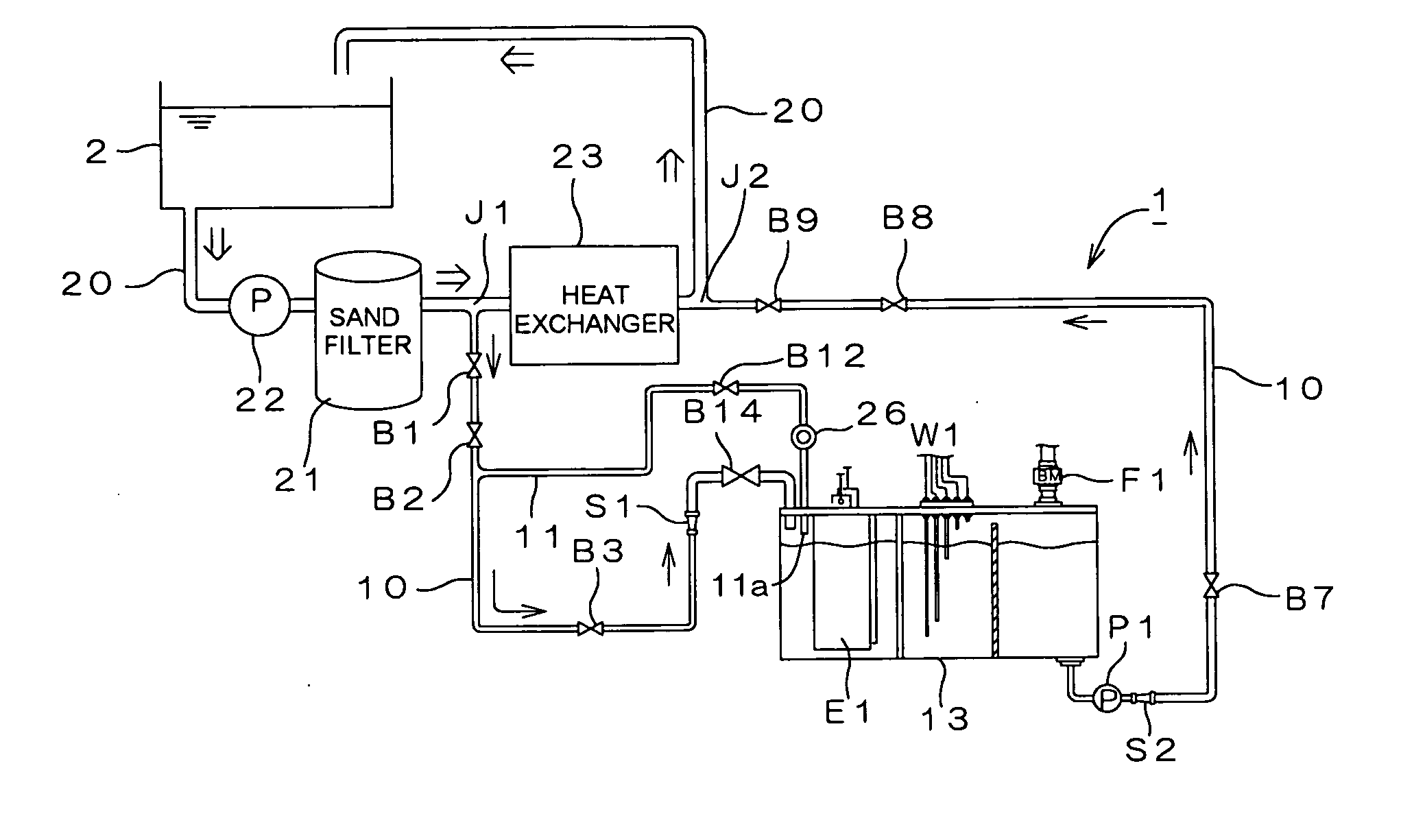
[0050] FIG. 1 is a diagram schematically illustrating the construction of a water treating device 1 incorporated in a large-scale water container 2 such as a swimming pool or a bathing pool in a bathhouse in accordance with the present invention.

[0051] Referring to FIG. 1, the water container 2 is provided with a main circulation line 20. The main circulation line 20 is provided with a circulation pump 22. Water is pumped out of the water container 2, circulated in a direction indicated by double-line arrows in the main circulation line 20, and fed back into the water container 2 by the circulation pump 22. A filter 21 for sand filtration of organic substances and a heat exchanger 23 for heating and cooling the circulated water are disposed downstream of the circulation pump 22 in the main circulation path 20.

[0052] A water treatment line 10 is diverged from the main circulation line 20 at a branch J1 located downstream of the filter 21 and upstream of the heat exchanger 23. The wat...

third embodiment

[0109] FIG. 10 is a diagram schematically illustrating the construction of a water treating device incorporated in a large-scale water container 2 in accordance with the present invention.

[0110] The construction of the water treating device shown in FIG. 10 is characterized in that a feed line 35 having a batch process electrolyzing chamber 14 as described in the second embodiment is connected parallel to a water treatment line 10 having an air / liquid separation chamber 13 as described in the first embodiment.

[0111] The water treating device shown in FIG. 10 is constructed such that a bypass line 41 is diverged from a main circulation line 20 and a residual chlorine sensor 20 is disposed in the bypass line as in the second embodiment. Therefore, the bypass line 11 and the residual chlorine sensor 26 provided in the water treatment line 10 in the first embodiment are not provided.

[0112] Alternatively, the construction of the first embodiment in which the bypass line 11 is provided in...


PUM

PropertyMeasurementUnit
Flow rateaaaaaaaaaa
Concentrationaaaaaaaaaa
Currentaaaaaaaaaa

Abstract

The present invention provides a water treating device, which comprises: a water container for containing water to be treated; an electrolyzing chamber for sterilizing the to-be-treated water by way of electrochemical decomposition through energization of an electrode set consisting of at least two electrode plates; a water treatment line through which the to-be-treated water is introduced into the electrolyzing chamber from the water container and fed back into the water container after the sterilization of the water in the electrolyzing chamber; a residual chlorine sensor for measuring the residual chlorine concentration of the to-be-treated water before the water is introduced into the electrolyzing chamber; and control means for controlling the amount of the to-be-treated water to be electrochemically decomposed in the electrolyzing chamber on the basis of the residual chlorine concentration measured by the residual chlorine sensor to keep the residual chlorine concentration of the water to be fed back into the water container within a predetermined range; wherein a bypass line is provided which is branched from the water treatment line at a position upstream of the electrolyzing chamber for sampling the to-be-treated water, introducing the sampled to-be-treated water into the residual chlorine sensor for the measurement of the residual chlorine concentration thereof, and discharging the sampled to-be-treated water into the electrolyzing chamber after the measurement. With this arrangement, the to-be-treated water subjected to the measurement of the residual chlorine concentration in the bypass line is returned into the electrolyzing chamber, so that no waste water is produced. Further, the to-be-treated water returned into the electrolyzing chamber is sterilized in the electrolyzing chamber, and then fed back into the water container. Therefore, water yet to be sterilized is not fed back into the water container.

Description

[0001] The present invention relates to a novel water treating device which is capable of sterilizing water contained in various types of water containers ranging from large-scale water containers such as swimming pools and bathing pools in bathhouses to medium-scale water containers such as water supply tanks on building rooftops and small-scale water containers such as bathtubs for general domestic use.PRIOR ART[0002] To maintain the quality of water in indoor and outdoor swimming pools or in bathing pools in hotels and public bathhouses, for example, the water is periodically sterilized by adding so-called chlorinated lime (bleaching powder or high-concentration bleaching powder) or an aqueous solution of sodium hypochlorite (NaClO) to the water in the pools.[0003] Conventionally, this operation is manually performed by workers in a swimming pool or a bathhouse. In addition, the chlorinated lime and the sodium hypochlorite aqueous solution are irritating, so that careful attentio...

Claims


Application Information

Patent Timeline
IPC IPC(8): C02F1/00C02F1/461C02F1/467C02F9/00
CPCC02F1/001C02F1/46104C02F2303/04C02F2301/046C02F1/4674C02F9/00C02F2103/42C02F2209/005C02F2209/05C02F2209/06C02F2209/29C02F2209/40C02F2209/42C02F2301/043C02F1/46C02F1/467
Inventor NAKANISHI, MINORUKISHI, MINORUINAMOTO, YOSHIHIROHIROTA, TATSUYAKAWAMURA, TAMOTSUKAWAMURA, YOZOKONDO, FUMITAKE
Owner SANYO ELECTRIC CO LTD
Why Eureka
Try Eureka