Apparatus and method for thermal sterilization of liquids

a technology of liquid sterilization and apparatus, applied in the direction of lavatory sanitory, water/sludge/sewage treatment, specific water treatment objectives, etc., can solve the problems of inability to achieve a sufficiently long dwell time and high sterilization temperature, and achieve the most temperature-resistant microbials. the most resistant to oxidation and other problems

Inactive Publication Date: 2004-08-19
LUTZER WILHELM
View PDF4 Cites 11 Cited by
  • Summary
  • Abstract
  • Description
  • Claims
  • Application Information

AI Technical Summary

Benefits of technology

[0007] The above objects have further been achieved according to the invention in a method of thermally sterilizing a liquid, including pressurizing the liquid to an elevated pressure above normal atmospheric pressure, flowing the pressurized liquid along a heat exchanger to pre-heat the liquid, flowing the pre-heated liquid through a heating zone where the liquid is heated to a sufficiently high sterilizing treatment temperature, flowing the treated liquid along the heat exchanger to transfer heat from the treated liquid via the heat exchanger to the inflowing liquid, whereby the treated liquid is cooled and the inflowing liquid is pre-heated, and then reducing the pressure of the out-flowing treated liquid.
[0008] According to a preferred feature of the invention, a substantial portion (e. g. a predominant proportion greater than 50% or even greater than 75%) of the heating energy required for heating the in-flowing liquid to the required thermal treatment temperature is provided by heat transfer from the out-flowing treated liquid in the counterflow heat exchanger. Thereby, the out-flowing liquid is cooled while the in-flowing liquid is pre-heated, and the substantial portion of the total required heating energy is retained within the pressure vessel. This improves the thermal efficiency of the process in the operation of the apparatus, so that the thermal sterilization becomes more economical, and also allows a higher treatment temperature to be achieved more quickly and maintained for a sufficient treatment dwell time.
[0009] According to further preferred features of the invention, a pressure increasing device such as a pressurizing pump is connected on the inlet side of the pressure vessel, while a pressure reducing device such as a pressure reducing turbine or expansion device is connected on the outlet side of the pressure vessel. The term "pump" is intended to have broad coverage of all devices that convey and pressurize a liquid. The pressure reducing device may have a similar construction as the pump, but operating in an opposite flow direction. Preferably, these two devices are connected to each other, for example through a suitable mechanical transmission or shaft, so that the energy recovered by the pressure reducing device while reducing the pressure of the pressurized liquid is provided to drive the pressure increasing device for pressurizing the liquid on its way into the pressure vessel. A motor may be additionally connected to the pressure increasing device to provide additional required drive power, for example to make up for mechanical power losses. In this manner, the pressurization cycle is also very efficient and economical. Only the minimal thermal and pressure energy losses must be added to the system, for example in the form of electrical energy supplied to the heater and to the pump motor.
[0011] This required dwell time at the required temperature of at least 200.degree. C. is advantageously achievable in a flow-through process with the apparatus and method according to the invention. This is especially achieved because of the combination of the high pressure and the pre-heating by heat exchange that is achieved in the pressure vessel in the inventive apparatus. Namely, the required temperature of 200.degree. C. is achieved at a high pressure of approximately 16 bar in the pressure vessel of the inventive apparatus. Operating at this high pressure allows the required high temperatures above the normal atmospheric boiling point of the liquid to be achieved, while still preferably maintaining the liquid in its liquid state throughout the treatment process.

Problems solved by technology

Problems arise in the conventional methods and apparatuses for achieving a thermal sterilization, due to a thermal inefficiency, which leads to an undesirable high energy consumption and / or makes it impossible to achieve sufficiently high sterilization temperatures for a sufficiently long dwell time to destroy the most temperature-resistant microbial contaminants or microorganisms.

Method used


Image

  • Apparatus and method for thermal sterilization of liquids
  • Apparatus and method for thermal sterilization of liquids

Examples


Embodiment Construction

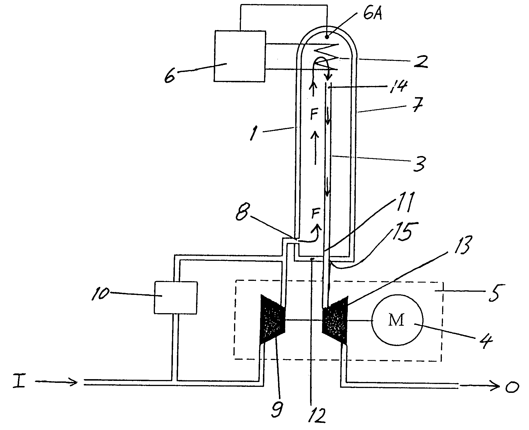
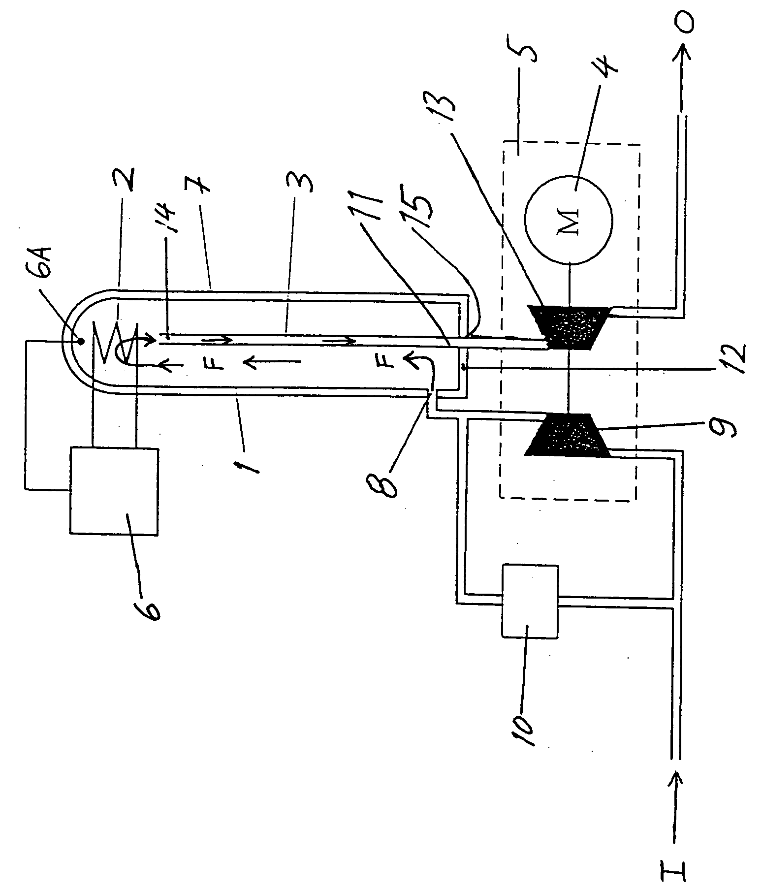
[0013] The exemplary apparatus according to the invention shown schematically in the single drawing FIGURE comprises a pressure vessel 1, a regulatable heater 2, preferably an electric resistance heater 2, arranged in a heating zone within the pressure vessel 1, a counterflow heat exchanger 3 arranged within the pressure vessel 1, and a pressurizing-depressurizing module or compression-expansion module 5. A regulator 6 is connected to the heater 2 and receives a temperature signal from a temperature sensor 6A arranged in the heating zone within the pressure vessel 1. Thereby, the regulator 6 applies e.g. electrical energy to the heater 2 in a regulated manner dependent on the temperature signal provided by the temperature sensor 6A, so as to regulate the operation of the heater 2 to achieve the required treatment temperature in the heating zone. The pressure vessel 1 is preferably surrounded and enclosed by any suitable conventionally known thermal insulation 1, and preferably has a...


PUM

PropertyMeasurementUnit
temperatureaaaaaaaaaa
pressureaaaaaaaaaa
temperatureaaaaaaaaaa

Abstract

A heater and a counterflow heat exchanger are arranged inside a pressure vessel, having an inlet connected to a pressurizing device and an outlet connected to a depressurizing device. To thermally sterilize a microbiologically contaminated liquid, the inflowing contaminated liquid is pressurized and pumped into the pressure vessel, where it is pre-heated by flowing along the heat exchanger and then heated to the required treatment temperature by the heater. The arising treated liquid is cooled by flowing along the heat exchanger and is then depressurized upon exiting the pressure vessel. Thermal energy is transferred from the outflowing liquid to the inflowing liquid by the heat exchanger. Pressure energy is transferred from the outflowing liquid to the inflowing liquid by the interconnected depressurizing and pressurizing devices. A high proportion of the total required energy is retained within the system, and high treatment temperatures (above the atmospheric boiling point) are efficiently achievable.

Description

PRIORITY CLAIM[0001] This application is based on and claims the priority under 35 U.S.C. .sctn.119 of German Patent Application 103 01 376.8, filed on Jan. 16, 2003, the entire disclosure of which is incorporated herein by reference.[0002] The invention relates to an apparatus and a method for thermally sterilizing or pasteurizing a liquid and especially water, for destroying microbiological contaminants, by flowing the liquid through a heating zone in which the water is heated to a sufficient treatment temperature for a sufficient treatment dwell time to destroy the target microbiological contaminants or microorganisms.BACKGROUND INFORMATION[0003] It is generally known to sterilize various liquids, such as drinking water and liquid foodstuffs by exposing the liquid to a sufficiently high temperature for a sufficiently long thermal treatment dwell time to destroy at least the desired high percentage of the target microbial contaminants or microorganisms. Such thermal sterilization ...

Claims


Application Information

Patent Timeline
Patent Type & Authority Applications(United States)
IPC IPC(8): A61L2/04C02F1/02
CPCA61L2/04C02F2303/04C02F2301/066C02F1/02
Inventor LUTZER, WILHELM
Owner LUTZER WILHELM
Why Eureka
Try Eureka