

Shape memory foam material
a foam material and shape technology, applied in the field of foam materials, can solve the problems of deterioration of foam material strength, poor mount operation, and insufficient fluid sealing, soundproofing,
- Summary
- Abstract
- Description
- Claims
- Application Information
AI Technical Summary
Benefits of technology
Problems solved by technology
Method used
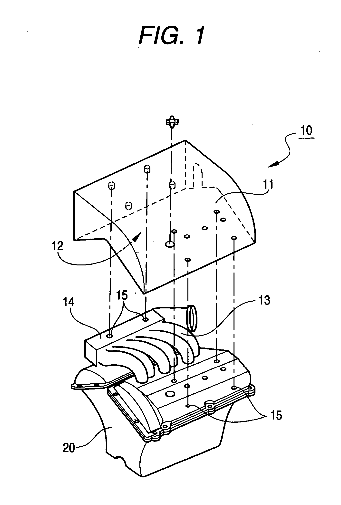
Image

Examples
embodiment 1
[0067] The same urethane foam as in the compressed by a thermal press of 100.degree. C. together with a spacer of 5 mm in thickness, and retained for about 5 minutes in the state. Then, the thermal press was cooled down to 25.degree. C. After the cooling operation, the pressure was released so as to produce a test piece.
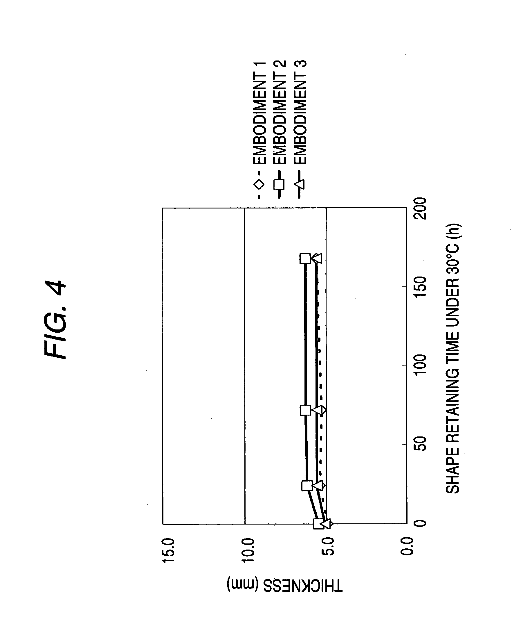
[0068] The test pieces of the embodiments were obtained by impregnating a urethane foam having a water absorption coefficient of 0.2 g / cm.sup.3 or more, and a bulk density of 100 kg / m.sup.3 or less with a thermoplastic resin having a glass transition point of 120.degree. C. or less or melting point of 120.degree. C. or less, heating and compressing, cooling down the same to a room temperature (25.degree. C.) while keeping the compressed state, and releasing the pressure after the cooling operation. In the embodiments 1, 2, the same thermoplastic resin was used, but the resin emulsion concentration and the impregnation amount according thereto differ. Moreover, the em...
embodiment embodiment embodiment 1 2 3 compression 120 120 120
1 TABLE 1 Embodiment Embodiment Embodiment 1 2 3 Compression 120 120 120 Temperature (.degree. C.) Base foam Material Urethane Urethane Urethane material Thickness 14.5 14.5 14.5 (mm) Bulk density 25 25 25 (kg / m.sup.3) Water 0.76 0.76 0.76 absorption coefficient (%) Thermoplastic Material Ethylene- Ethylene- Ethylene-substance vinyl vinyl vinyl material acetate- acetate- acetate- vinyl vinyl acrylate chloride chloride copolymer copolymer copolymer Concen- 50 25 50 tration (%) Glass 50 50 -- transition point (.degree. C.) Melting ---- 72 point (.degree. C.) Amount of thermoplastic 0.042 0.025 0.032 substance impregnation (g / cm.sup.3) Thickness after the shape 4.9 5.5 5.1 retaining operation (mm)
[0070]
PUM
| Property | Measurement | Unit |
|---|---|---|
| density | aaaaa | aaaaa |
| density | aaaaa | aaaaa |
| softening temperature | aaaaa | aaaaa |
Abstract
Description
Claims
Application Information