
Endless belt and method of manufacturing the endless belt

Inactive Publication Date: 2004-08-26
TOHO KASEI CO LTD
View PDF7 Cites 11 Cited by
  • Summary
  • Abstract
  • Description
  • Claims
  • Application Information

AI Technical Summary

Benefits of technology

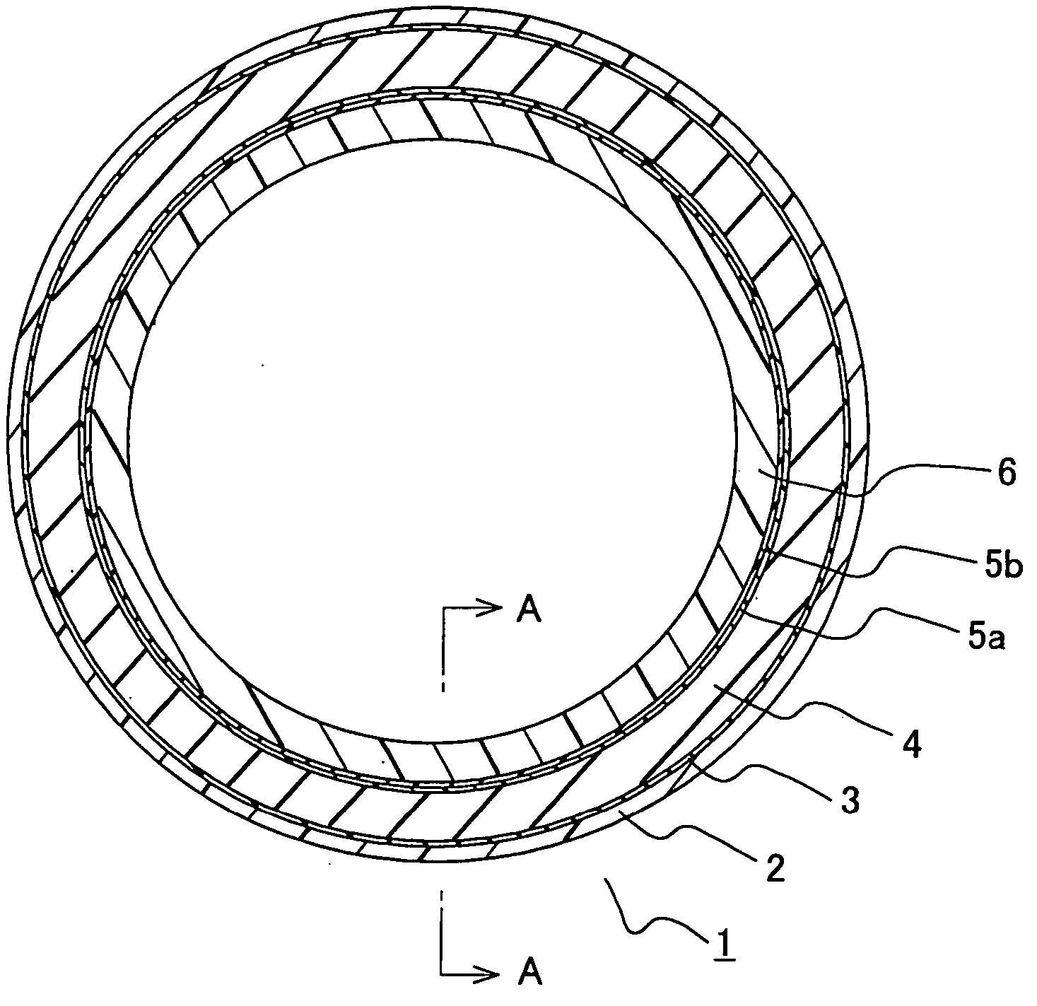
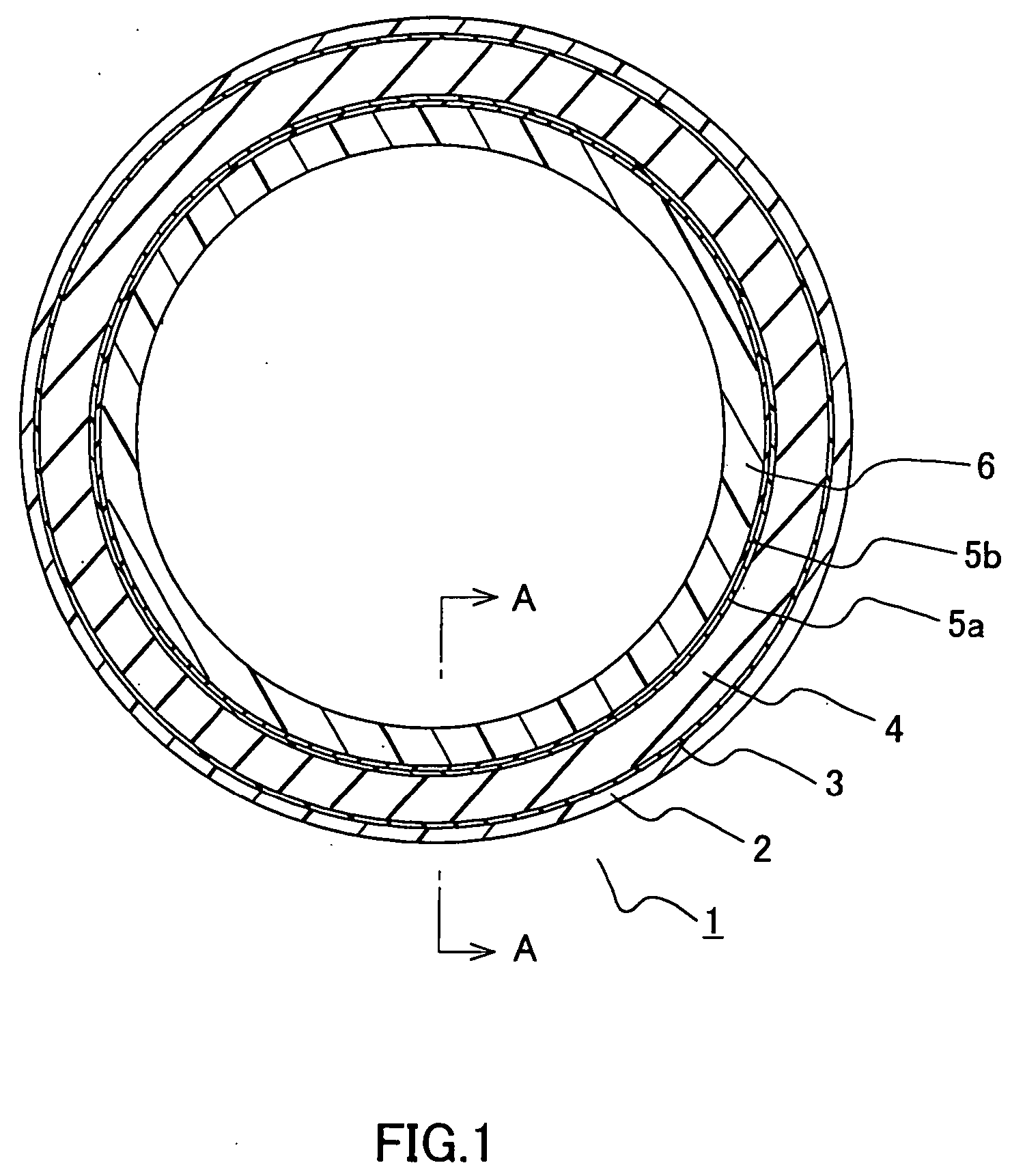
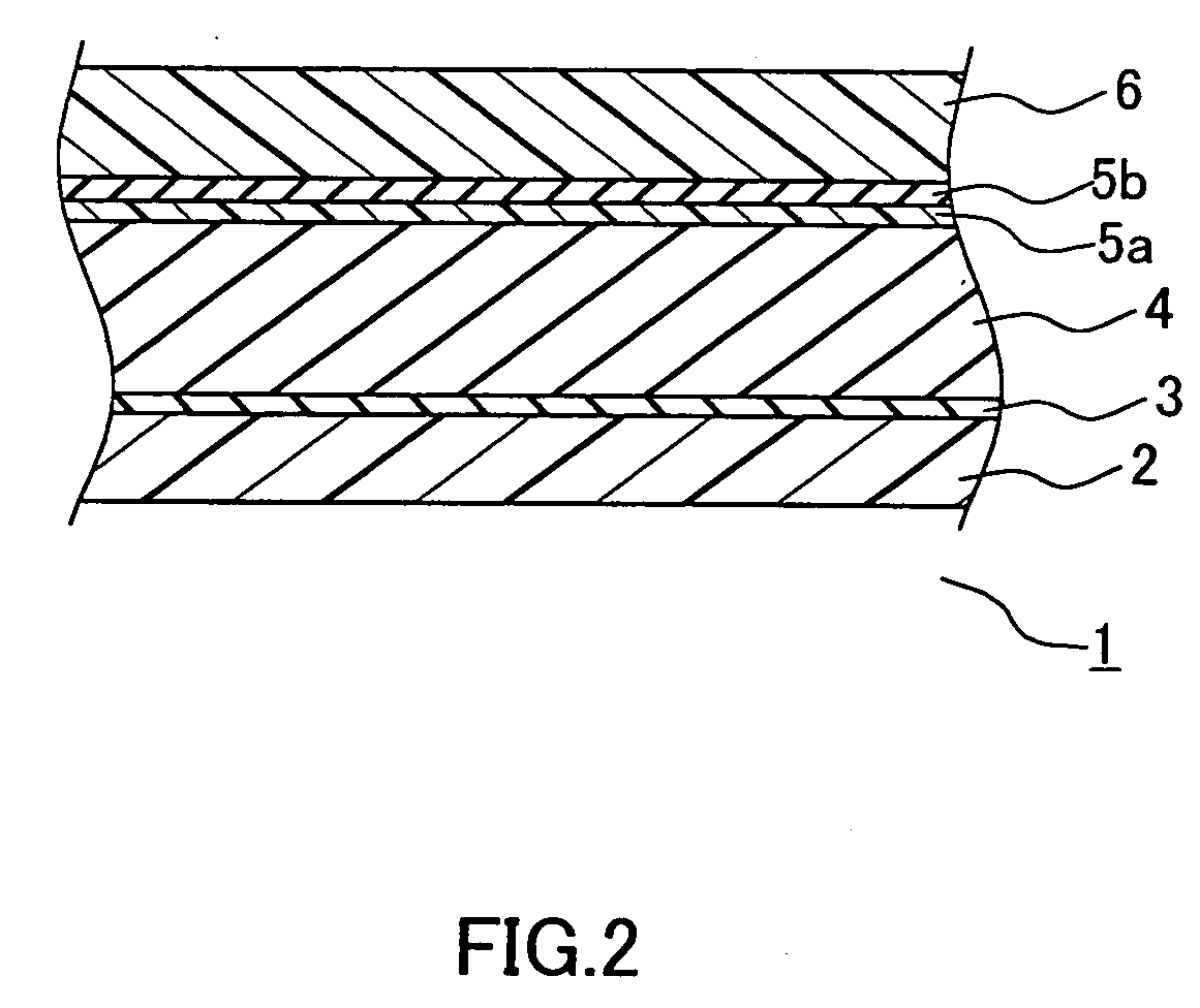
[0013] Since the endless belt of the present invention comprises a release layer as an outermost layer, the belt has an excellent release property. Furthermore, since the outer surface of the release layer is formed of a molded surface, the outer surface of the release layer is smooth, and has a superior release property to that of a release layer formed of a mold-free surface. It is to be noted here that the molded surface is referred to as a surface having contacted a die during molding. On the other hand, the mold-free surface is referred to as a surface not having contacted a die during molding.
[0068] Furthermore, it is preferred that the adhesive layer be formed of two layers which are formed of a primer for silicone rubber having a thickness of 1 to 5 .mu.m and a fluoro rubber primer having a thickness of 1 to 5 .mu.m, respectively. This is because owing to the two-layer structure, the adhesion between the elastic layer and the support layer can be more strengthened. Examples usable for the primer for the silicone rubber here are silan coupling agents such as vinylsilan, acrylsilan, epoxysilan, aminosilan and the like. Furthermore, examples usable for the fluoro rubber primer are fluoro rubbers VDF-HFP type, VDF-HFP-TFE type, VDF-PFP type, VDF-PFP-TFE type, VDF-PFMVE-TFE type, VDF-CTFE type, and the like.

Problems solved by technology

On the one hand, this heat roller fixing method is suitable for high speed copying because of keeping the heat roller in its entirety at a given temperature, but on the other hand, it has a drawback in its long waiting time.
More specifically, at the time of starting the operation of the apparatus, it is necessary to heat the heat roller to a given temperature, so that there occurs a long waiting time between when a power supply is switched on and when the apparatus becomes able to be operated.
Moreover, since the heat roller in its entirety needs to be heated, the power consumption is high.
However, in the case where a conventional fixing belt is used for a fixing unit in a full color laser beam printer, the belt does not have enough elasticity of a surface thereof to be able to sufficiently surround the color toners.
As a result, it was difficult to fuse the color toners and satisfactory fixing could not be realized.
However, the conventionally used release layer formed of a fluoro rubber has had a problem in that it causes insufficient fixing property and release property of the toners.
Accordingly, if this method is employed such that a fluororesin layer is baked on an outer surface of an elastic layer formed of silicone rubber, which has a heat resistant temperature of about 250.degree. C., then the silicone rubber layer is hardened by heat and loses its elasticity.

Method used


Image

  • Endless belt and method of manufacturing the endless belt
  • Endless belt and method of manufacturing the endless belt
  • Endless belt and method of manufacturing the endless belt

Examples


example 2

[0078] An endless belt according to Example 2 of the present invention was obtained in a manner similar to that as in Example 1, except that a tetrafluoroethylene-perfluoroalkoxyethylene copolymer (product of DuPont Company: "540CL") having, as an additive, 2.5 wt % of conductive carbon was used here for the release layer. No wrinkles were observed on the thus obtained endless belt.

example 3

[0079] A molding die was prepared, which was formed of a pipe made of stainless steel (SUS304) having an inner diameter of 60 mm, a thickness of 3 mm and a mirror-polished outer circumferential surface. On the outer circumferential surface of the molding die, a polytetrafluoroethylene (product of Daikin Industries, Ltd.: "ED-4839BD") provided with electrical conductivity was coated to a thickness of 35 .mu.m as a release layer, and thereafter was baked at 380.degree. C. for 15 minutes. After the baking, the thickness of the release layer was 20 .mu.m.

[0080] Next, the molding die was cooled to room temperature, and thereafter the surface of the release layer was subjected to etching treatment using a fluororesin treatment agent "Tetra-Etch".

[0081] Subsequently, on the release layer, a silicone rubber (product of Shinetsu Silicone Co., Ltd.: "KE-1241"), as an elastic layer, was coated and was baked at 250.degree. C. for 30 minutes. After the baking, the elastic layer had a thickness o...

example 4

[0083] An endless belt according to Example 4 of the present invention was obtained in a manner similar to that as in Example 1, except that here the support layer (thickness of 80 .mu.m) formed of the polyimide varnish (product of I.S.T Corporation: "RC-5057") was made to contain a filler made of a heat generating material. For the heat generating material, silver flakes having an average particle size of 9 .mu.m was used. The mixing ration of the polyimide varnish to the silver flakes was: polyimide varnish / silver flakes =1 / 2 in terms of volume ratio. No wrinkles were observed on the surface of the thus obtained endless belt.


PUM

PropertyMeasurementUnit
Temperatureaaaaaaaaaa
Elasticityaaaaaaaaaa
Heataaaaaaaaaa

Abstract

An annular endless belt (1), comprising a release layer (2) formed of fluororesin and having an outer surface formed of a molded surface disposed as an outermost layer, a support layer (6) disposed as an innermost layer, and an elastic layer (4) disposed between the outermost layer and the innermost layer, whereby the fluororesin layer as the release layer can be formed by coating on the outer surface of the endless belt without hardening the elastic layer thereof used as the fixing belt of a color copying machine.

Description

[0001] The present invention relates to an endless belt used, e.g., for a full color image fixing belt, which is employed in a fixing unit for fixing, by heating, toner images transferred to a transfer member such as a transfer paper or the like in an apparatus such as an electrophotographic copying machine, a fax machine, a printer or the like, and also to a method of manufacturing the same.[0002] In an image forming apparatus such as an electrophotographic copying machine, a fax machine, a printer or the like, toners on, e.g., a transfer paper as a transfer member are heated and fused at a final stage of printing or copying, and are fixed on the transfer paper.[0003] A general method of such fixing is a heat fixing method. Conventionally, a heat roller fixing method is widely used therefor. According to the heat roller fixing method, a pair of rollers composed of a rubber roller and a heat roller, which has a thermal heater inside thereof and has an outer circumference coated with...

Claims


Application Information

Patent Timeline
IPC IPC(8): B29C41/22B29C41/42B29C41/46B29D29/00B29K27/12B29K77/00B29K83/00B32B1/08B32B27/30G03G15/20
CPCB29C41/22B29C41/42B29C41/46B29D29/00B29K2027/12Y10T428/1393B29K2995/0013B29K2995/0046B29L2031/709G03G15/2057G03G2215/2016B29K2105/0047Y10T428/31536Y10T428/3154B32B27/28
Inventor YOSHIDA, HARUHIKOHIGUCHI, TAKESHIMATUI, RYOHEIMAEDA, YOSHIKO
Owner TOHO KASEI CO LTD
Learn More