Supercharge Your Innovation With Domain-Expert AI Agents!

Method of manufacturing connecting rods

a manufacturing method and technology of connecting rods, applied in the direction of manufacturing tools, connecting rod bearings, transportation and packaging, etc., can solve the problems of inefficiency or obsolete of many previously known manufacturing methods of connecting rods, and the failure rate of fracture splitting techniques has approached 40% in some previously known methods, so as to increase the efficiency of the manufacturing process and cost and time savings

Active Publication Date: 2004-09-16
MD INVESTORS CORP
View PDF5 Cites 2 Cited by
  • Summary
  • Abstract
  • Description
  • Claims
  • Application Information

AI Technical Summary

Benefits of technology

[0011] In view of the above, a primary object of the present invention is to increase the efficiency of the manufacturing process and provide cost and time savings in the connecting rod manufacturing process through a reduction in the number and type of machines required to mass produce connecting rods, specifically through the use of a five work station process.
[0012] Another object of the present invention to reduce the capital investment required to tool such manufacturing lines through the use of machinery capable of interchangeable tooling.
[0013] Yet another object of the present invention is to increase the spatial efficiency of the manufacturing process so that the floor space required for such manufacturing lines can be reduced, thereby reducing overhead.

Problems solved by technology

Because large numbers of parts are manufactured each year according to the above-identified manufacturing process, any efficiency in manufacture can result in substantial cost and time savings.
These highly specific dimensions and tolerances render many of the previously known methods of manufacturing connecting rods either inefficient or obsolete.
However, as discussed in U.S. Pat. No. 4,198,879 (incorporated by reference herein), failure rates for fracture splitting techniques have approached 40% in some previously known methods.
Moreover, many of the previously known methods did not provide for a means of consistently and efficiently mass producing connecting rods having the necessary tolerances and dimensions, such that additional boring, grinding and honing (as mentioned above) was often needed, thereby resulting in added costs in terms of machinery and spatial requirements along the manufacturing line itself.

Method used


Image

  • Method of manufacturing connecting rods
  • Method of manufacturing connecting rods
  • Method of manufacturing connecting rods

Examples


Embodiment Construction

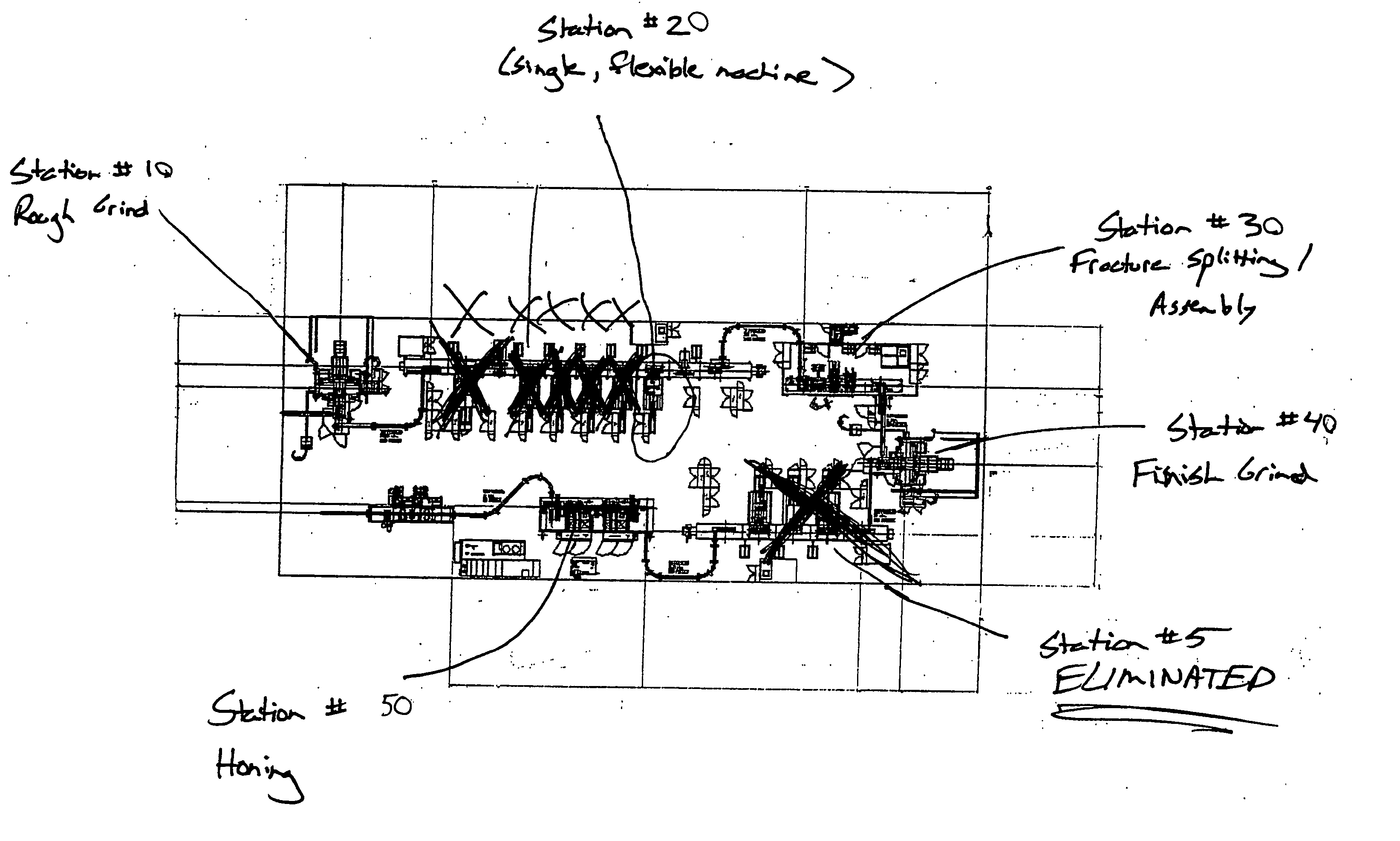
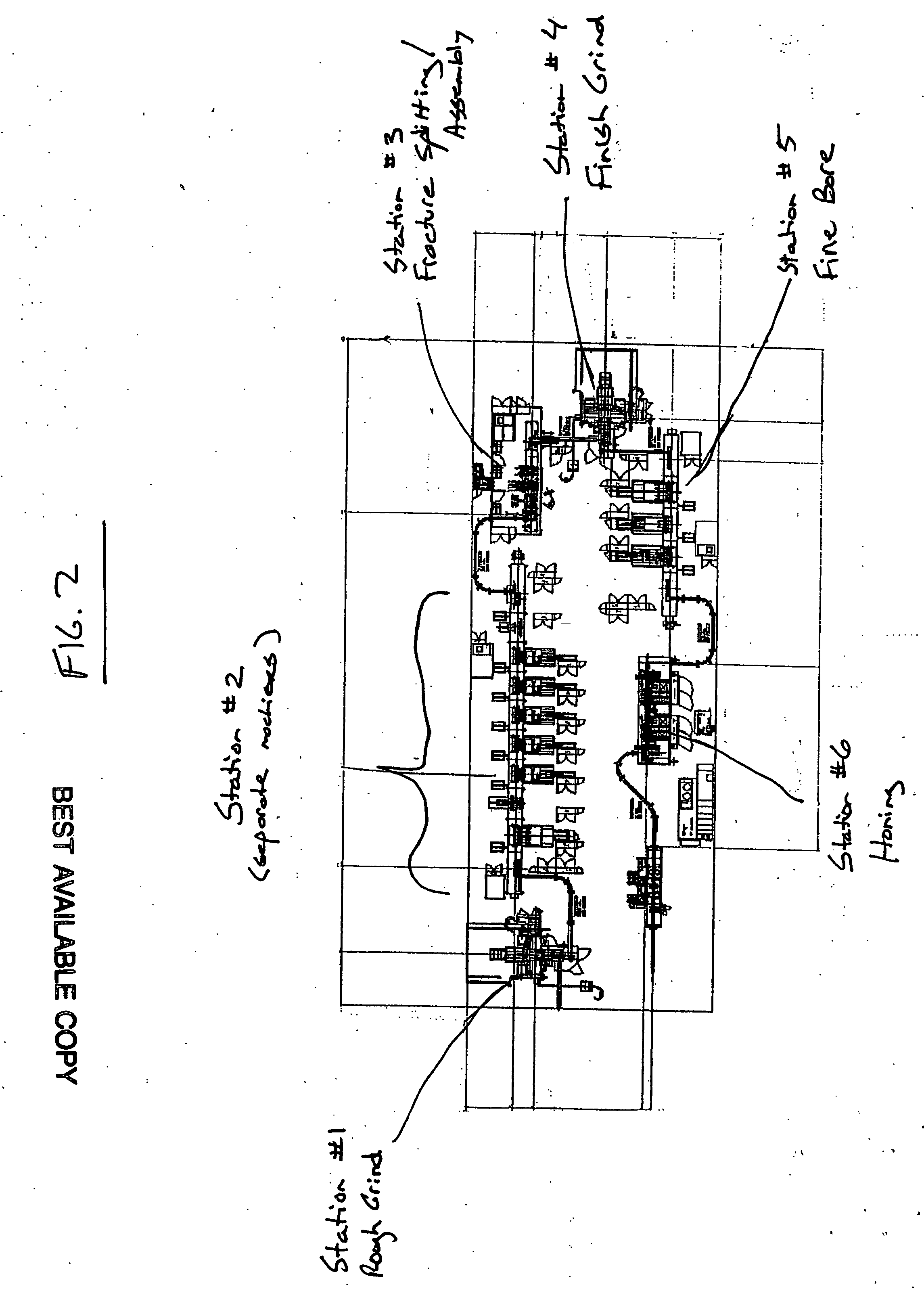
[0020] The present invention provides a process and method for manufacturing connecting rods that reduces the steps performed in the prior art so as to increase efficiency and reduce capital and overhead investments. Particularly, the present invention provides for all necessary boring and drilling operations to be performed prior to fracture splitting. Another aspect of the present invention is to perform numerous manufacturing operations on a single, flexible machine having automatic tool change capabilities and fixtures that allow spindles to machine the connecting rod from different sides of the component thereby reducing floor space required and reducing the capital investment required in purchasing separate manufacturing machines. Finally, the invention may be incorporated into existing plant equipment, without the need for investment in new fracture splitting equipment or machinery (particularly, machinery relying upon lasers or other highly specialized technological innovati...


PUM

PropertyMeasurementUnit
thrustaaaaaaaaaa
flexibleaaaaaaaaaa
fractureaaaaaaaaaa

Abstract

A streamlined method for the mass production of connecting rods is disclosed, with particular applicability for anticipated in the production of rods made from powdered metal materials. The method contemplates the rough grinding of a work piece, followed by the use of a single, flexibly tooled boring machine to create crank and pin bores. The work piece is then fracture split, subjected to a final grinding process and honed to specific tolerances without the need for final boring. The entire inventive process may be implemented on a five work station assembly line, thereby reducing the capital investment in machinery and space required by previously known methods.

Description

[0001] This application claims priority to a provisional Serial No. 60 / 436,105, filed Dec. 23, 2003.[0002] This invention relates to the manufacture of engine parts, and more particularly to the method of manufacturing connecting rods.[0003] Connecting rods are needed for all sizes and types of engines. A typical engine connecting rod 10, shown in FIG. 1, has an apertured large end encompassing a crank bore 20 adapted for installation about a crankshaft journal. The smaller apertured end encompassing a pin bore 24 is connected to the piston assembly to transfer power from the engine to the drive train. The shank 26 connects the two ends.[0004] In the past, connecting rods were manufactured from solid steel blanks. Grinding and boring operations fashioned the blank to the desired specifications. More recently, powder metal has been used to more accurately and efficiently create preformed connecting rod blanks that are then subjected to standard grinding and boring operations. A brief...

Claims


Application Information

Patent Timeline
Patent Type & Authority Applications(United States)
IPC IPC(8): B23D31/00B23P15/00F16C7/02F16C9/04
CPCB23D31/003B23P15/00B23P2700/04Y10T29/5176F16C9/045Y10T29/5136Y10T29/49288F16C7/023Y10T225/35
Inventor HAEHNEL, MICHAEL
Owner MD INVESTORS CORP
Features
  • R&D
  • Intellectual Property
  • Life Sciences
  • Materials
  • Tech Scout
  • Unparalleled Data Quality
  • Higher Quality Content
  • 60% Fewer Hallucinations
Learn More