Recording multiple spatially-heterodyned direct to digital holograms in one digital image

a digital image and heterodyne technology, applied in the field of recording multiple spatial heterodyned direct to digital holograms in one digital image, can solve the problems of difficulty in tracking the phase change in the object image, the noise in each individual image is not correlated to the noise in the other image, and the error in the measured height of the object, so as to reduce the spread or carryover of information, reduce common-mode or correlated noise, and increase the height range of measurement

Active Publication Date: 2004-10-28
UT BATTELLE LLC
View PDF24 Cites 35 Cited by
  • Summary
  • Abstract
  • Description
  • Claims
  • Application Information

AI Technical Summary

Benefits of technology

0056] Never before has a technique been shown for acquiring two holograms at different wavelengths substantially simultaneously on one CCD. This type of simultaneous acquisition is not possible without the use of the direct to digital holographic technique involving spatial heterodyning of the object image (i.e., spatially-heterodyned holograms). Without the use of spatial heterodyning, it is not possible to separate the two holograms acquired substantially simultaneously on one CCD camera. Because the inventors use the interference of the object and reference beams to generate precise linear fringes to spatially heterodyne the object hologram, the inventors discovered that they can generate a second spatially-heterodyned hologram at a different spatial frequency by introducing a second optical beam into the optics system. As noted above, the different spatial frequencies can be defined by focusing the two set of beams (object and reference) onto the focal (image) plane of a CCD at two different angles. By generating the second spatially-heterodyned hologram at a different spatial carrier frequency, the two images (of approximately the same object area) can be separated and processed independently even though they are acquired in a single CCD image. The invention can include combining or mixing of (e.g., subtracting) the phase and/or object images from these two holograms to transform the scale length of the measured phase shift in each image to the difference phase at the beat wavelength of the two images.
0057] The invention can include measuring objects with spatial height variations much greater than the imaging laser wavelength over lateral distances smaller than the wavelength.
0058] The invention can include reduction of common-mode or correlated noise, such as back reflections and vibrations, by acquiring the two spatially-heterodyned digital holograms substantially simultaneously on the same CCD and subtracting the resulting phase and/or amplitude images.
0059] An alternative embodiment of the invention can include the mixing of the two 3-dimensional images in Fourier space rather than af...

Problems solved by technology

(1-2) A limitation of this technology is the difficulty of tracking the phase change in the object image when it involves multiple 2.pi. steps.
This unwrapping is often prone to errors, resulting in errors in the measured height of the object.
A serious limitation of this known approach is that noise in each individual image is uncorrelated to...

Method used


Image

  • Recording multiple spatially-heterodyned direct to digital holograms in one digital image
  • Recording multiple spatially-heterodyned direct to digital holograms in one digital image
  • Recording multiple spatially-heterodyned direct to digital holograms in one digital image

Examples


example 1

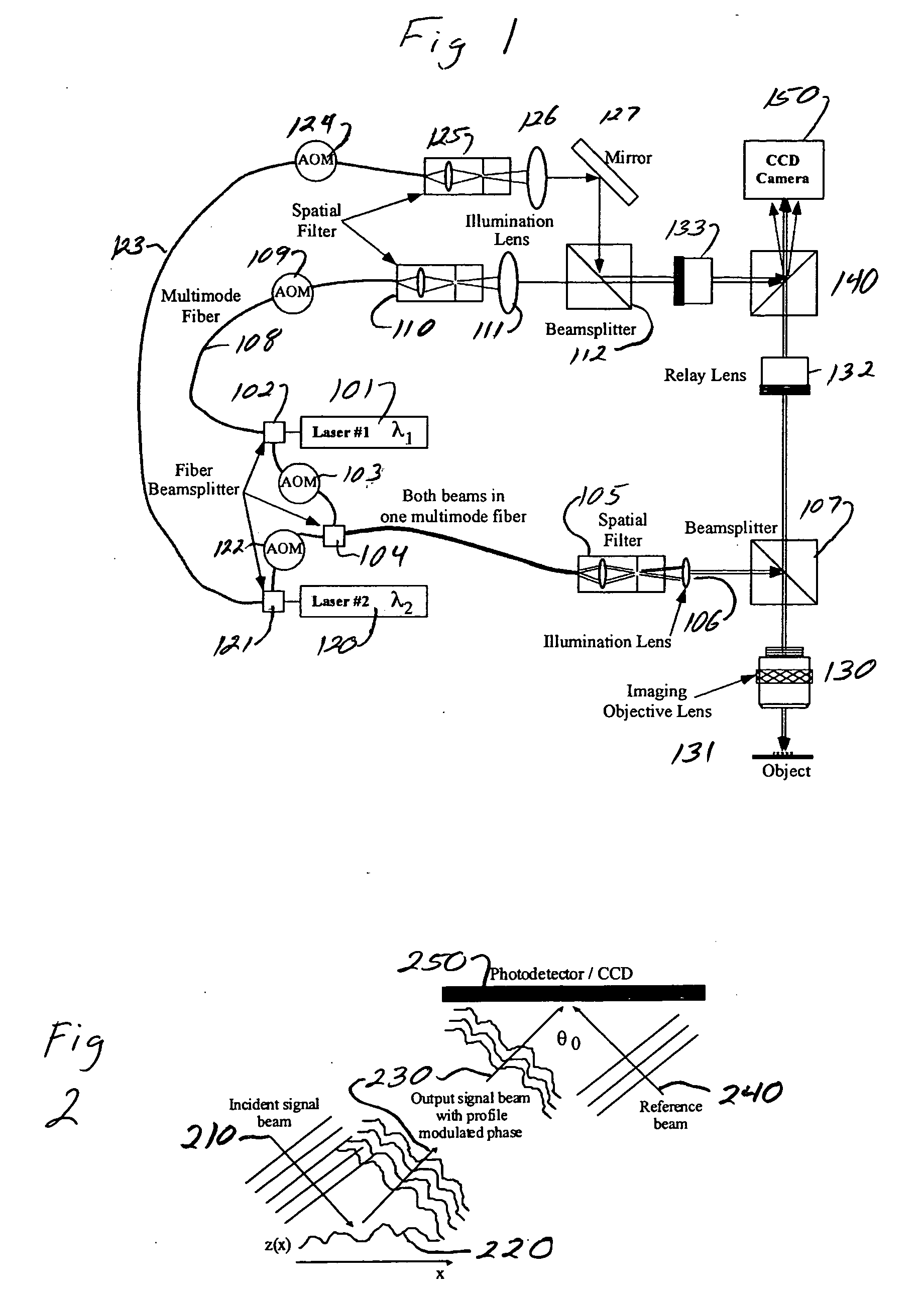
[0110] Referring to FIG. 11, a free space exemplary embodiment of the invention is depicted using reference mirrors. A first laser 1101 operating at a wavelength A, is optically coupled to a beamsplitter 1103. A beamsplitter 1105 is optically coupled to the beamsplitter 1103. An illumination lens 1107 is optically coupled to the beamsplitter 1105. A beamsplitter 1109 is optically coupled to the illumination lens 1107. An imaging lens 1110 is optically coupled to the beamsplitter 1109. An area of a surface of an object 1112 of interest is optically coupled to the imaging lens 1110. An illumination lens 1111 is optically coupled to the beamsplitter 1103. A beamsplitter 1113 is optically coupled to the illumination lens 1111. An imaging lens 1115 is optically coupled to the beamsplitter 1113. A reference mirror 1117 is optically coupled to the imaging lens 1115. A beamsplitter 1119 is optically coupled the beamsplitter 1113.

[0111] Still referring to FIG. 11, a second laser 1121 operati...

example 2

[0112] Referring to FIG. 12, a free space exemplary embodiment of the invention is depicted where reference mirrors are omitted. A helium neon laser 1201 operating at a wavelength of 611.9 nanometers is optically coupled to a variable attenuator 1203. A variable beamsplitter 1205 is optically coupled to the variable attenuator 1203. A spatial filter 1207 is optically coupled to the variable beamsplitter 1205. A collimating lens 1209 is optically coupled to the spatial filter 1207. A beamsplitter 1211 is optically coupled to the collimating lens 1209. An illumination lens 1213 is optically coupled to the beamsplitter 1211. A beamsplitter 1215 is optically coupled to the illumination lens 1213. An objective lens 1217 is optically coupled to the beamsplitter 1215. A target 1219 having a surface area of interest is optically coupled to the objective lens 1217. A tube lens 1220 is optically coupled to the beamsplitter 1215. A spatial filter 1221 is optically coupled to the variable beams...

example 3

[0116] Referring to FIG. 13, an exemplary embodiment of the invention is depicted that uses optical fibers and reference mirrors. A laser 1301 operating at a wavelength of A, is optically coupled to a beamsplitter 1303. An optical fiber 1304 is coupled to the beamsplitter 1303. A beamsplitter 1305 is coupled to the fiber 1304. A fiber 1306 is coupled to the beamsplitter 1305. An illumination lens 1307 is optically coupled to the fiber 1306. A beamsplitter 1309 is optically coupled to the illumination lens 1307. An imaging lens 1311 is optically coupled to the beamsplitter 1309. A object 1313 having an area of interest is optically coupled to the imaging lens 1311. An optical fiber 1315 is coupled to the beamsplitter 1303. An illumination lens 1317 is optically coupled to the fiber 1315. A beamsplitter 1319 is optically coupled to the illumination lens 1317. An imaging lens 1321 is optically coupled to the beamsplitter 1319. A reference mirror 1323 is optically coupled to the imaging...


PUM


Abstract

Systems and methods are described for recording multiple spatially-heterodyned direct to digital holograms in one digital image. A method includes digitally recording, at a first reference beam-object beam angle, a first spatially-heterodyned hologram including spatial heterodyne fringes for Fourier analysis; Fourier analyzing the recorded first spatially-heterodyned hologram by shifting a first original origin of the recorded first spatially-heterodyned hologram to sit on top of a first spatial-heterodyne carrier frequency defined by the first reference beam-object beam angle; digitally recording, at a second reference beam-object beam angle, a second spatially-heterodyned hologram including spatial heterodyne fringes for Fourier analysis; Fourier analyzing the recorded second spatially-heterodyned hologram by shifting a second original origin of the recorded second spatially-heterodyned hologram to sit on top of a second spatial-heterodyne carrier frequency defined by the second reference beam-object beam angle; applying a first digital filter to cut off signals around the first original origin and define a first result; performing a first inverse Fourier transform on the first result; applying a second digital filter to cut off signals around the second original origin and define a second result; and performing a second inverse Fourier transform on the second result, wherein the first reference beam-object beam angle is not equal to the second reference beam-object beam angle and a single digital image includes both the first spatially-heterodyned hologram and the second spatially-heterodyned hologram.

Description

[0001] This application is a continuation-in-part of, and claims a benefit of priority under 35 U.S.C. 120 from copending utility patent application U.S. Ser. No. 10 / 421,444, filed Apr. 23, 2003, the entire contents of which are hereby expressly incorporated herein by reference for all purposes.[0003] 1. Field of the Invention[0004] The invention relates generally to the field of direct-to-digital interferometry (spatial-heterodyne holography). More particularly, the invention relates to methods and machinery for obtaining two-wavelength differential-phase direct to digital interferograms (spatially-heterodyned holograms).[0005] 2. Discussion of the Related Art[0006] The techniques and apparatus of basic direct to digital interferometry (holography) are well known to those of skill in the art..sup.(1-2) A limitation of this technology is the difficulty of tracking the phase change in the object image when it involves multiple 2.pi. steps. A 2.pi. phase change occurs every time the o...

Claims


Application Information

Patent Timeline
IPC IPC(8): G03H1/04G03H1/08G03H1/28
CPCG03H1/0406G03H1/0443G03H1/0866G03H1/265G03H1/28G03H2001/0456G03H2001/046G03H2001/0469G03H2226/11G03H2226/13
Inventor HANSON, GREGORY R.BINGHAM, PHILIP R.
Owner UT BATTELLE LLC
Why Eureka
Try Eureka