
Patent application for a computer motional command interface

a command interface and computer technology, applied in the field of computer peripherals and motion recognition, can solve problems such as distortion, nonlinearity, and inability to solve problems, and achieve the effects of less tedium, increased personal realism of interaction, and less tedium

Inactive Publication Date: 2004-12-16
CEHELNIK THOMAS G
View PDF10 Cites 25 Cited by
  • Summary
  • Abstract
  • Description
  • Claims
  • Application Information

AI Technical Summary

Benefits of technology

[0030] The present invention uses receivers with high input impedance so as not to draw currents or distort the field. Also, in the passive mode, the frequencies of operation are that of or near the electrical power line frequency and are surely quasistatic. These frequencies are extremely low, and substantially reduce the conductivity of objects near to the sensor. Thus preventing field distortions.
[0032] It is one aspect of this invention to make computers and robots more human-like by increasing the personal realism of interacting with these devices through a motional command system (MCS) that offers a friendly and efficient means of interfacing the user's motional commands and body language with the computer.
[0033] It is another aspect of the invention to provide a personal computer interface that responds more efficiently with less tedium than using pointing device peripherals.
[0034] It is another aspect of the invention to allow the user of the MCS to interact more naturally, and be more mobile and active will interacting with a computer.
[0043] Yet another aspect of the invention is provide a method for processing MCS body language commands whereby the computer can recognize moods and emotions or matters of urgency of the user and thus responds with helpful processes and gives a personality to a computer.

Problems solved by technology

Thus distortion may occur and contribute to nonlinearities.
If objects of low electrical potential are near, they will distort the potential field and affect the measurement accuracy by reducing current arriving at the receive electrodes.
These frequencies are extremely low, and substantially reduce the conductivity of objects near to the sensor.

Method used


Image

  • Patent application for a computer motional command interface
  • Patent application for a computer motional command interface
  • Patent application for a computer motional command interface

Examples


Embodiment Construction

[0048] To those skilled in of electronics will recognize the variation of the technology.

[0049] The local background noise characteristic of the A.C. line and computer signals are detected and modulated by the presence of the user's command surface in the vicinity of the motional command system (MCS) sensors. Here the command surface is referred to as the hand or body part issuing the motional command.

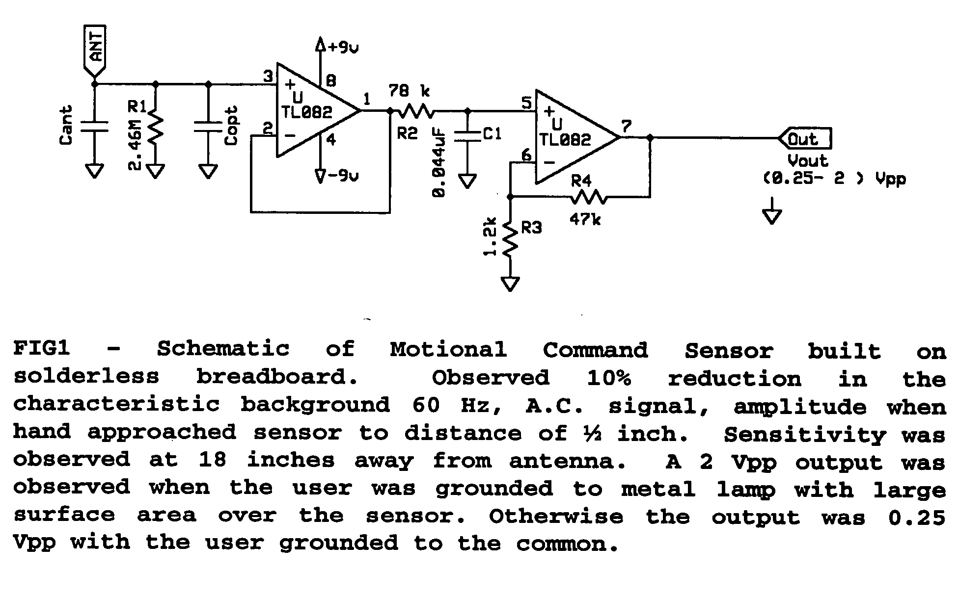
[0050] FIG. 1 describes the sensor as consisting of a small 4 in. long antenna with an amplifier assembled on a solderless breadboard. The input stage is a buffer amplifier with high input impedance, followed by a low pass filter and then an amplification stage.

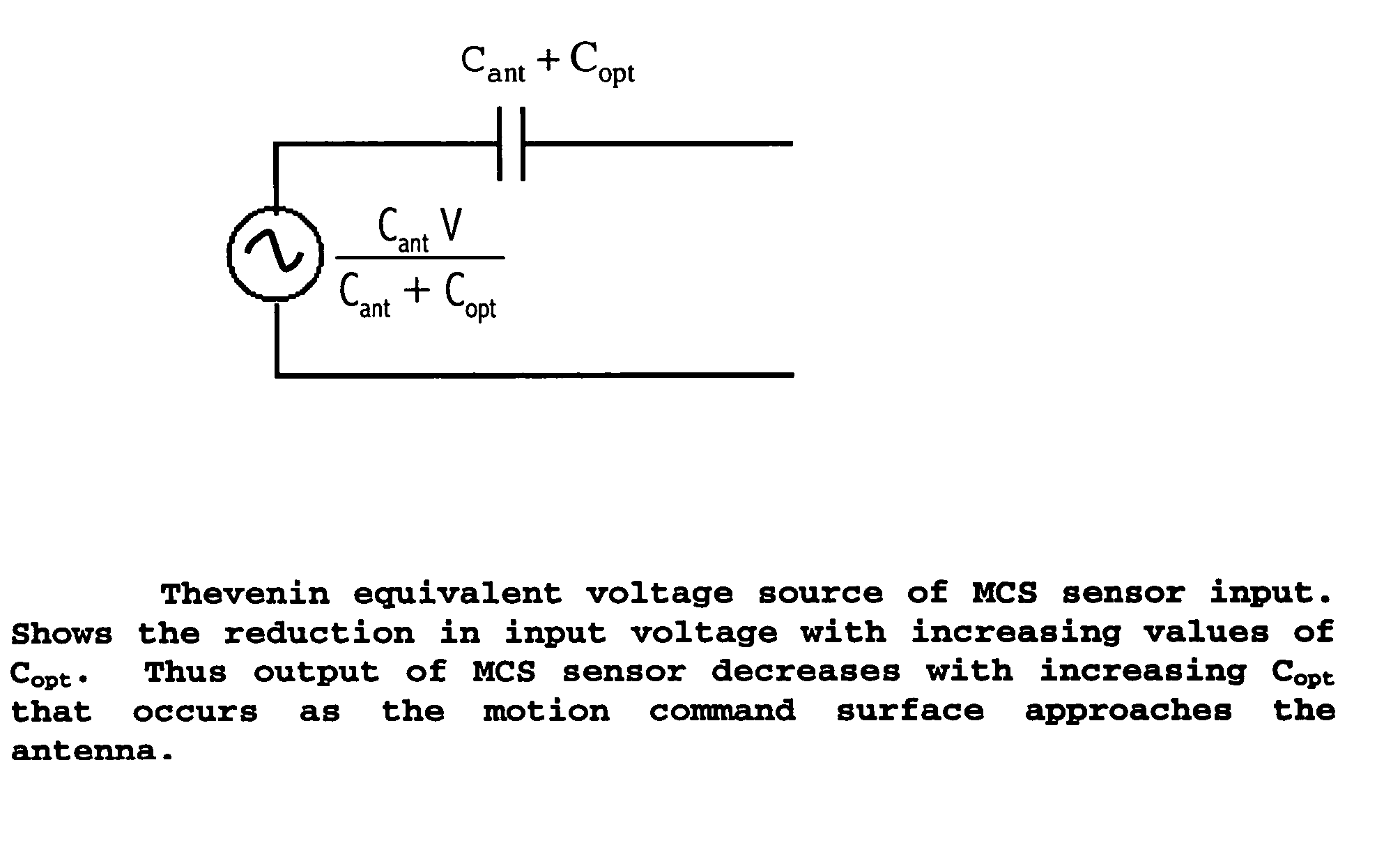
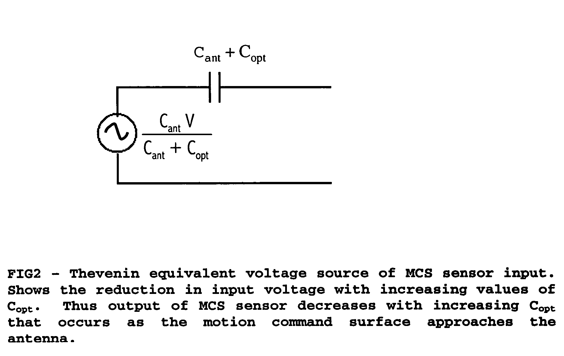
[0051] At the low frequency of 50-60 Hz of the A.C. line, the antenna acts as an equivalent electric source in series with a capacitor represented in FIG. 1 as C.sub.ant. To understand this model, we recall that the conductor is an equipotential surface maintained at a potential determined from the background electric fields. No...


PUM


Abstract

A method and apparatus is described for interacting with electronic devices via motional commands. The method uses perturbations of the background quasistatic electric fields. The apparatus measures perturbations in electric potential relative to the background. Body movement is recognized by comparing changes in signals in time with signals collected from training sets for specified motional commands or gestures. Upon recognizing the commands, the apparatus issues the predetermined response to the motion.

Description

[0001] This application is to receive benefit of 60 / 445,548 filed Feb. 6, 2003 and 60 / 515844 filed Oct. 30, 2003.STATEMENT OF FEDERALLY SPONSORED RESEARCH OR DEVELOPMENT[0002] Not applicableREFERENCE SEQUENCE LISTING OR COMPUTER PROGRAM[0003] Sequence listing is not applicable. A computer program using MATLAB language is provided to demonstrate a motional command recognition algorithm.BACKGROUND OF THE INVENTION--FIELD OF INVENTION[0004] This invention relates to fields of computer peripherals and motion recognition for the control of electronic apparatus, specifically to aid in the input of commands to computerized devices, and to add artificial intelligence features to a user interface. It is related to proximity and motion sensing of a person and objects.[0005] The ability to communicate with a computer through peripherals has been developing for years from the punch card, CRT, DOS keyboard line commands, windows type programs using the mouse, light pens and stylists, to speech r...

Claims


Application Information

Patent Timeline
IPC IPC(8): G01R27/26G06F3/01
CPCG01V3/088G06F3/011G08B31/00
Inventor CEHELNIK, THOMAS G.
Owner CEHELNIK THOMAS G
Learn More