
Air conditioner device with trailing electrode

a technology of trailing electrodes and air conditioners, which is applied in the direction of electrostatic separation, energy-based chemical/physical/physicochemical processes, electric supply techniques, etc., can solve the problems of doubling the size of electric motors, causing substantial noise, and hazard to children, so as to enhance the flow of negative ions, enhance the flow of particle collection, and enhance the airflow velocity

Inactive Publication Date: 2005-01-06
THE SHARPER IMAGE
View PDF97 Cites 69 Cited by
  • Summary
  • Abstract
  • Description
  • Claims
  • Application Information

AI Technical Summary

Benefits of technology

[0033] One aspect of the present invention is to provide an electro-kinetic air transporter-conditioner that produces an enhanced airflow velocity, enhanced particle collection, and an appropriate amount of ozone production.
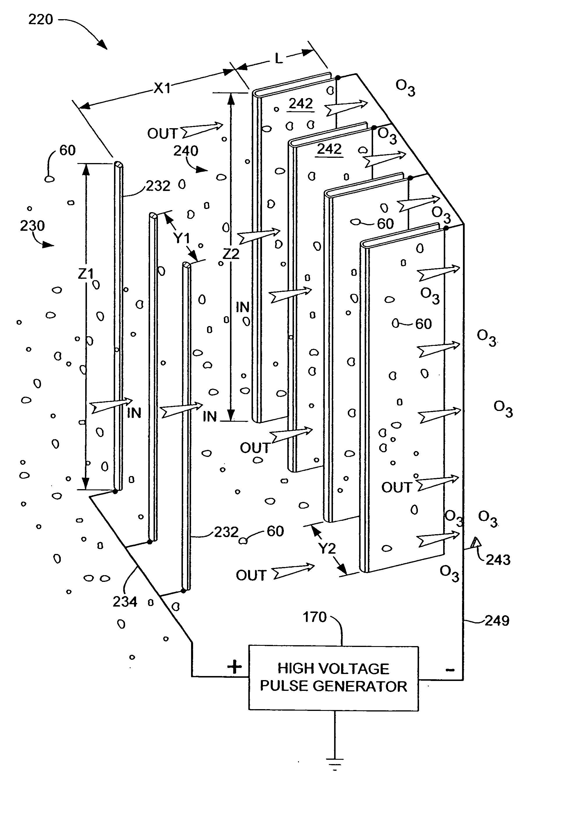
[0035] Another embodiment includes one or more trailing electrodes. Each trailing electrode can be located downstream of a second electrode. The trailing electrode can assist in neutralizing the amount of ions exiting this embodiment of the invention, and can further assist in collecting ionized particles. The trailing electrode can alternatively enhance the flow of negative ions from the transporter-conditioner. Additionally, the trailing electrodes can improve the laminar flow properties of the airflow exiting the air transporter-conditioner.
[0037] In yet another embodiment of the invention, one or more of the second electrodes are formed to have an enhanced protective end or trailing surface which assists in the operation and cleaning of the embodiment.

Problems solved by technology

Unfortunately, such fans produce substantial noise, and can present a hazard to children who maybe tempted to poke a finger or a pencil into the moving fan blade.
Unfortunately, the resistance to airflow presented by the filter element may require doubling the electric motor size to maintain a desired level of airflow.
Further, HEPA-compliant filter elements are expensive, and can represent a substantial portion of the sale price of a HEPA-compliant filter-fan unit.

Method used


Image

  • Air conditioner device with trailing electrode
  • Air conditioner device with trailing electrode
  • Air conditioner device with trailing electrode

Examples


Embodiment Construction

[0052] Overall Air Transporter-Conditioner System Configuration:

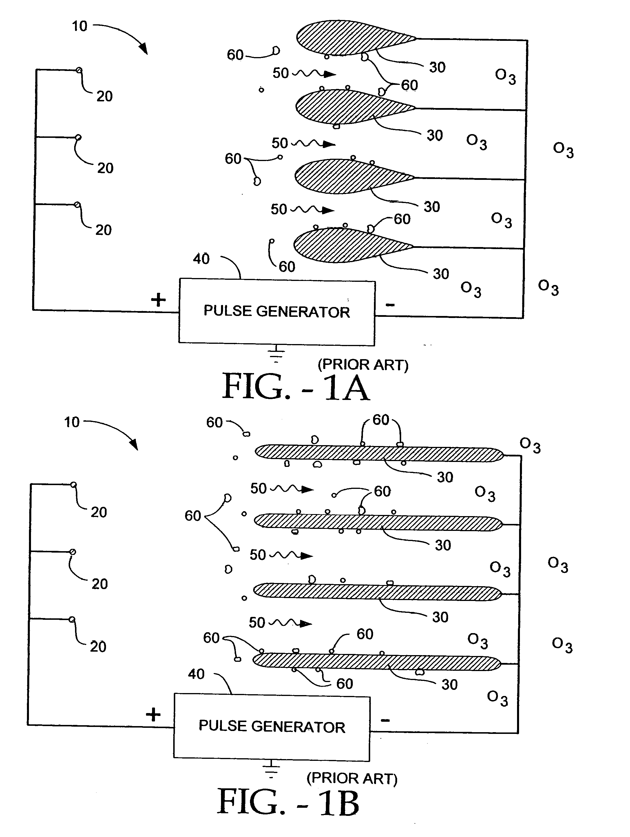
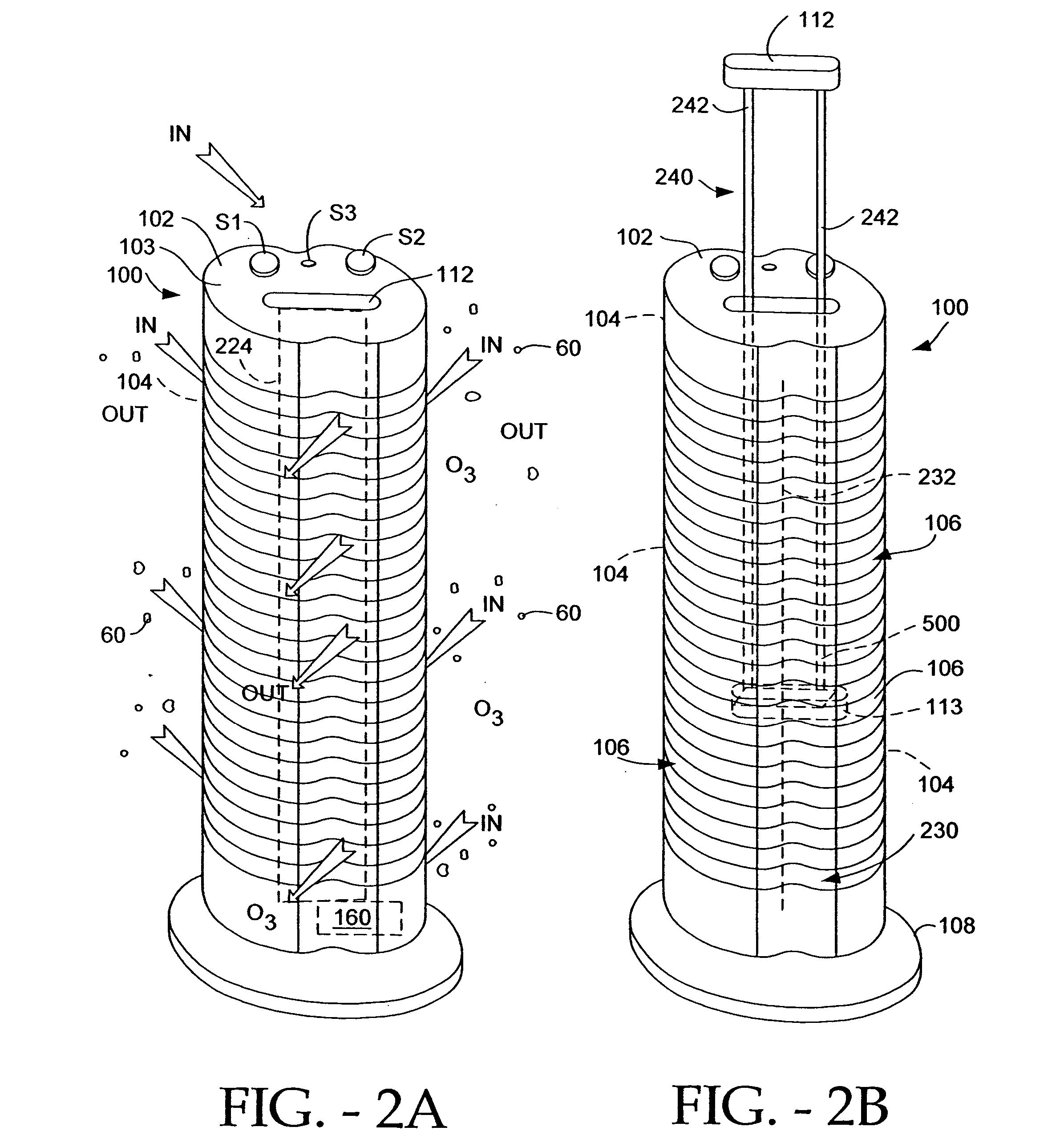
[0053]FIGS. 2A and 2B depict an electro-kinetic air transporter-conditioner system 100 whose housing 102 includes preferably rear-located intake vents or louvers 104 and preferably front located exhaust vents 106, and a base pedestal 108. If desired a single vent can provide and be used as both an air intake and an air exhaust with an air inlet channel and an air exhaust channel communicating with the vent and the electrodes. Preferably the housing is freestanding and / or upstandingly vertical and / or elongated. Internal to the transporter housing is an ion generating unit 160, preferably powered by an AC:DC power supply that is energizable or excitable using switch S1. S1, which along with the other below described user operated switches are conveniently located at the top 103 of the unit 100. Ion generating unit 160 is self-contained in that other ambient air, nothing is required from beyond the transporter housing, sa...


PUM

PropertyMeasurementUnit
widthaaaaaaaaaa
widthaaaaaaaaaa
widthaaaaaaaaaa

Abstract

An electro-kinetic air conditioner for removing particulates from the air creates an airflow using no moving parts. The conditioner includes an ion generator that has an electrode assembly including a first array of emitter electrodes, a second array of collector electrodes, and a high voltage generator. Preferably, a third or leading or focus electrode is located upstream of the first array of emitter electrodes, and / or a trailing electrode is located downstream of the second array of collector electrodes. The device can also include an interstitial electrode located between collector electrodes, an enhanced collector electrode with an integrally formed trailing end, and an enhanced emitter electrode with an enhanced length in order to increase emissitivity.

Description

CROSS-REFERENCE TO RELATED APPLICATIONS [0001] This application is a divisional of co-pending application entitled “ELECTRO-KINETIC AIR TRANSPORTER-CONDITIONER DEVICES WITH TRAILING ELECTRODE,” U.S. patent application Ser. No. 10 / 074,209, filed Feb. 12, 2002 which claims priority from the U.S. Provisional Patent Application No. 60 / 341,090, filed Dec. 13, 2001 under 35 U.S.C. 119(e). The co-pending patent application Ser. No. 10 / 074,209, claims priority from U.S. Provisional Patent Application No. 60 / 306,479, filed Jul. 18, 2001 under 35 U.S.C. 119(e). The co-pending patent Application Ser. No. 10 / 074,209, also claims priority from and is a continuation-in-part of U.S. patent application Ser. No. 09 / 924,624 filed Aug. 8, 2001 which is a continuation of U.S. patent application Ser. No. 09 / 564,960 filed May 4, 2000, now U.S. Pat. No. 6,350,417, which is a continuation-in-part of U.S. patent application Ser. No. 09 / 186,471 filed Nov. 5, 1998, now U.S. Pat. No. 6,176,977. The co-pending ...

Claims


Application Information

Patent Timeline
Patent Type & Authority Applications(United States)
IPC IPC(8): B01D53/32B03C3/12B03C3/74C01B13/11H01T23/00
CPCB01D53/32H01T23/00B01D2251/104B03C3/08B03C3/12B03C3/32B03C3/36B03C3/68B03C3/743B03C3/88B03C2201/08B03C2201/14B03C2201/28C01B13/11C01B13/115C01B2201/12C01B2201/20C01B2201/22C01B2201/62F24F2003/1682F24F2003/1685B01D53/323F24F8/30F24F8/40
Inventor TAYLOR, CHARLES E.LEE, JIM L.
Owner THE SHARPER IMAGE
Learn More