Low-noise preamplifier, in particular, for nuclear magnetic resonance (NMR)

a preamplifier and low-noise technology, applied in differential amplifiers, dc-amplifiers with dc-coupled stages, amplifiers, etc., can solve the problems of high noise factor, complex input resistance of gasfet preamplifier arrangement, etc., and achieve the effect of 1.2 db and 1.2 db

Active Publication Date: 2005-01-06
BRUKER BIOSPIN MRI
View PDF5 Cites 14 Cited by
  • Summary
  • Abstract
  • Description
  • Claims
  • Application Information

AI Technical Summary

Benefits of technology

[0010] The principle of operation of the circuit is based on the fact that the first transformer maps part of the output current, with proper phase, to the input of the preamplifier and to the amplifying element thereby changing, in particular reducing, the input impedance of the preamplifier. The inventive circuit permits free selection of the input resistance of the inventive preamplifier via the first transformer. Due to the high-ohmic input of the amplifying element, there is a substantial current flow between the input of the preamplifier and ground only via the secondary winding of the first transformer. The current flow through the secondary winding of the first transformer is determined by the induction acting in this secondary winding. The current induced in the secondary winding can thereby be adjusted via the winding ratio in the first transformer. In this manner, the input impedance of the preamplifier can be selected, in accordance with Ohm's law, through suitable selection of the winding ratio of the first transformer.
[0024] In an alternative, also preferred embodiment of the inventive preamplifier, a capacitor having a capacitance C is connected upstream of the electronic amplifying element to optimise the noise factor largely independently of the impedance adjustment, the capacitor C cooperating with the inductance L of the secondary winding of the first transformer to minimize the noise factor for a predetermined frequency, via the L / C ratio. The amplifying element can thereby be operated at its noise optimum and the predetermined frequency may also be above 400 MHz. A frequency range is thereby accessible which cannot be accessed with the broadband, second transformer. In accordance with the invention, the noise factor is first optimised via the L / C ratio, and the input impedance of the preamplifier is then adjusted through the first transformer, thereby maintaining the noise optimum.

Problems solved by technology

However, the input resistance of the GASFET preamplifier arrangement is complex, having a real portion of only 1 to 3 ohms.
In other preamplifiers which can be used in a broadband range, defined input impedances of e.g. 50 ohms can be established, however, the noise factors which can be obtained are quite high, i.e. approximately 1.2 dB.

Method used


Image

  • Low-noise preamplifier, in particular, for nuclear magnetic resonance (NMR)
  • Low-noise preamplifier, in particular, for nuclear magnetic resonance (NMR)
  • Low-noise preamplifier, in particular, for nuclear magnetic resonance (NMR)

Examples


Embodiment Construction

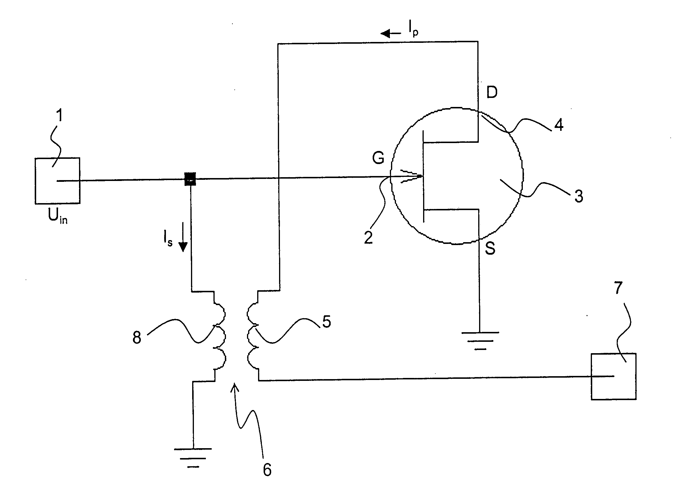
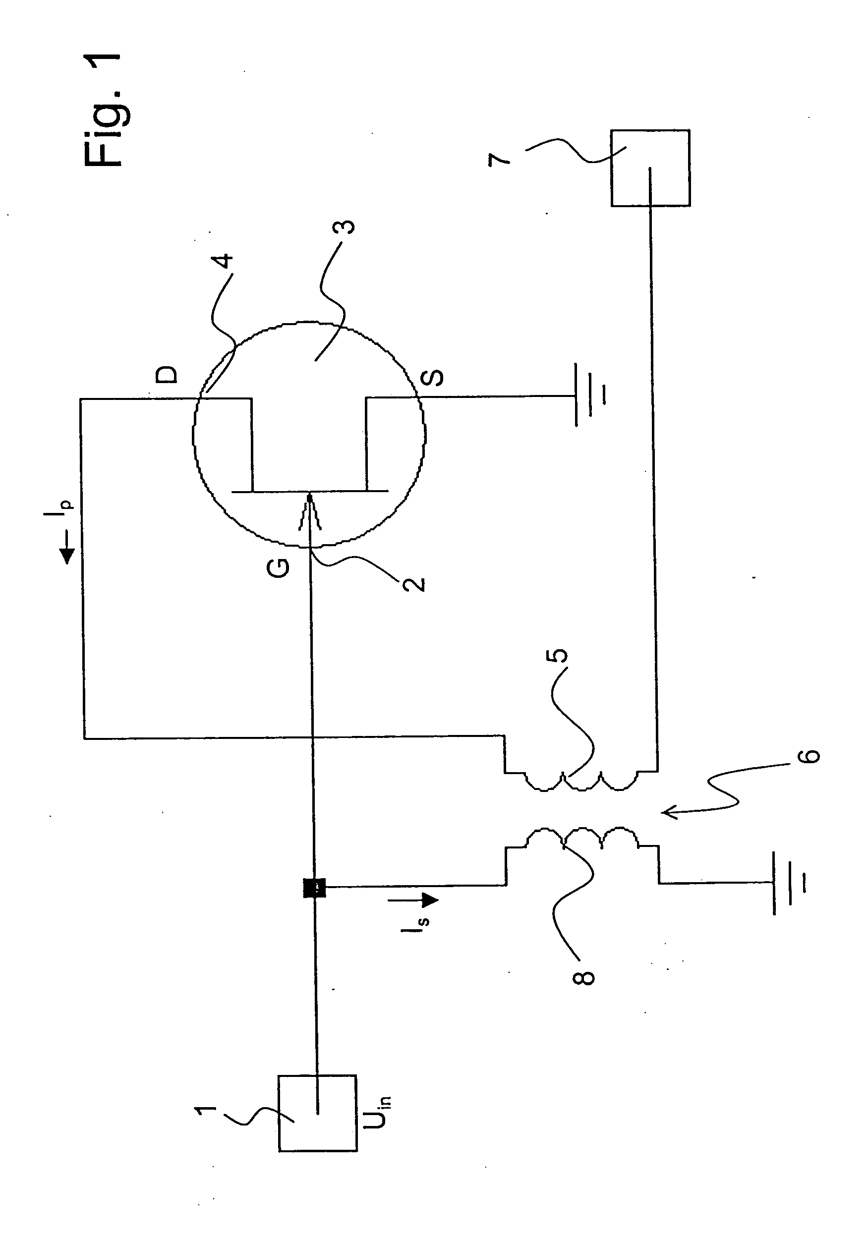
[0030]FIG. 1 shows a circuit diagram of a simple embodiment of the inventive preamplifier. This circuit is mainly suited for low frequencies below 100 MHz. An input voltage Uin is applied at an input 1 of the preamplifier. The input 1 of the preamplifier is connected to an input 2 of an amplifying element, namely gate G of a field effect transistor (FET) 3. The source S of the FET is connected to ground. The drain D of the FET 3 forms the output 4 of the amplifying element. The signal at the output 4 of the amplifying element is passed through a primary coil 5 of a first transformer 6 and applied to an output 7 of the preamplifier. A primary current Ip flows in the current line between the output 4 of the amplifying element and the output 7 of the preamplifier.

[0031] The first transformer 6 also has a secondary coil 8. One end thereof is connected to ground and the other end is connected to the input 1 of the preamplifier and to the input 2 of the amplifying element. A secondary cu...


PUM


Abstract

A low-noise preamplifier with an electronic amplifying element having an input (2) and an output (4), and with a first transformer (6) having a primary winding (5) and a secondary winding (8) is characterized in that the input (2) of the electronic amplifying element is the base of a transistor, the gate (G) of a field effect transistor (FET) or the grid of a vacuum tube, and the output (4) of the electronic amplifying element is the collector, the drain (D) or the anode, the output current (Ip) being passed from the electronic amplifying element through the primary winding (5) of the first transformer (6) to the output (7) of the preamplifier, wherein the secondary winding (8) of the first transformer (6) is connected to the input (2) of the electronic amplifying element. This preamplifier can be operated with extremely low noise and at any input impedance, in particular, at 50 ohms or 75 ohms.

Description

[0001] This application claims Paris Convention priority of DE 103 25 634.2 filed Jun. 6, 2003 the complete disclosure of which is hereby incorporated by reference. BACKGROUND OF THE INVENTION [0002] The invention concerns a low-noise preamplifier with an electronic amplifying element having an input and an output, and with a first transformer having a primary winding and a secondary winding. [0003] A preamplifier of this type has been disclosed by the circuit diagram of a preamplifier in NMR spectrometer CXP 100 of the company Bruker in 1980. [0004] Preamplifiers are used in all electronic fields to amplify signals, in particular currents, to a level suited for a downstream connected electronic component. One fundamentally tries to keep the signal-to-noise ratio large during the amplifying process. The quality factor thereby used is the so-called noise factor. [0005] For the amplification of alternating current signals, the input impedance of the preamplifier must also be taken int...

Claims


Application Information

Patent Timeline
Patent Type & Authority Applications(United States)
IPC IPC(8): G01R33/36H03F1/26H03F1/34
CPCG01R33/3621H03F1/26H03F2200/541H03F2200/534H03F1/347G01R33/32G01R33/3628
Inventor RATZEL, DIETER
Owner BRUKER BIOSPIN MRI
Why Eureka
Try Eureka