Micromachine production method

a micro-machine and production method technology, applied in the direction of fluid pressure measurement, fluid pressure measurement by electric/magnetic elements, instruments, etc., can solve the problems of further growth of above-described dishing problems, inability to obtain desired frequency characteristics, and inability to produce desired electrodes of desired shapes, etc., to achieve excellent electric characteristics, high accuracy, and high accuracy

Inactive Publication Date: 2005-01-06
SONY CORP
View PDF7 Cites 8 Cited by
  • Summary
  • Abstract
  • Description
  • Claims
  • Application Information

AI Technical Summary

Benefits of technology

[0023] Further, chemical mechanical planarization using cerium oxide slurry is applied to the polishing of the insulating film, whereby the polishing of the insulating film formed in the shape of trapezoidal section on the first electrode may be carried out without causing the dishing on the insulating film formed on the substrate. Thus, variations in thickness of the first electrode and the stopper film are solely confined within the limits of thickness variations created at the time of film deposition. As a result, the space between the first electrode and the second electrode on the first electrode may be obtained in a desired shape, and permits electric characteristics according to the design value to be obtained when the micromachine is used as a high frequency filter.
[0024] As described above, according to the micromachine production method of the present invention, after formation of the first electrode having, on the surface, the stopper film, the insulating film (the second insulating film) is formed, and the polishing of the second insulating film is carried out to planarize the second insulating film and also to expose the stopper film to the outside, so that no dishing is caused on the first electrode and the stopper film. The opening is formed in the stopper film on the first electrode, the sacrifice film is buried in the opening, the second electrode is formed on the sacrifice film and the removal of the sacrifice film is then carried out to form the space, so that the spatial gap between the first electrode and the second electrode...

Problems solved by technology

However, practically, large dishing arises so that an output electrode of a desired shape is not obtainable.
When the above dishing arises, a space to be formed between the output electrode and the vibrator electrode is hardly formed according to a design value, and as a result, desired frequency characteristics are not obtainable.
The above-described dishing problem is further growing particularly with an increase in a wide output electrode.
However, the above polishing stopp...

Method used


Image

  • Micromachine production method
  • Micromachine production method
  • Micromachine production method

Examples


Embodiment Construction

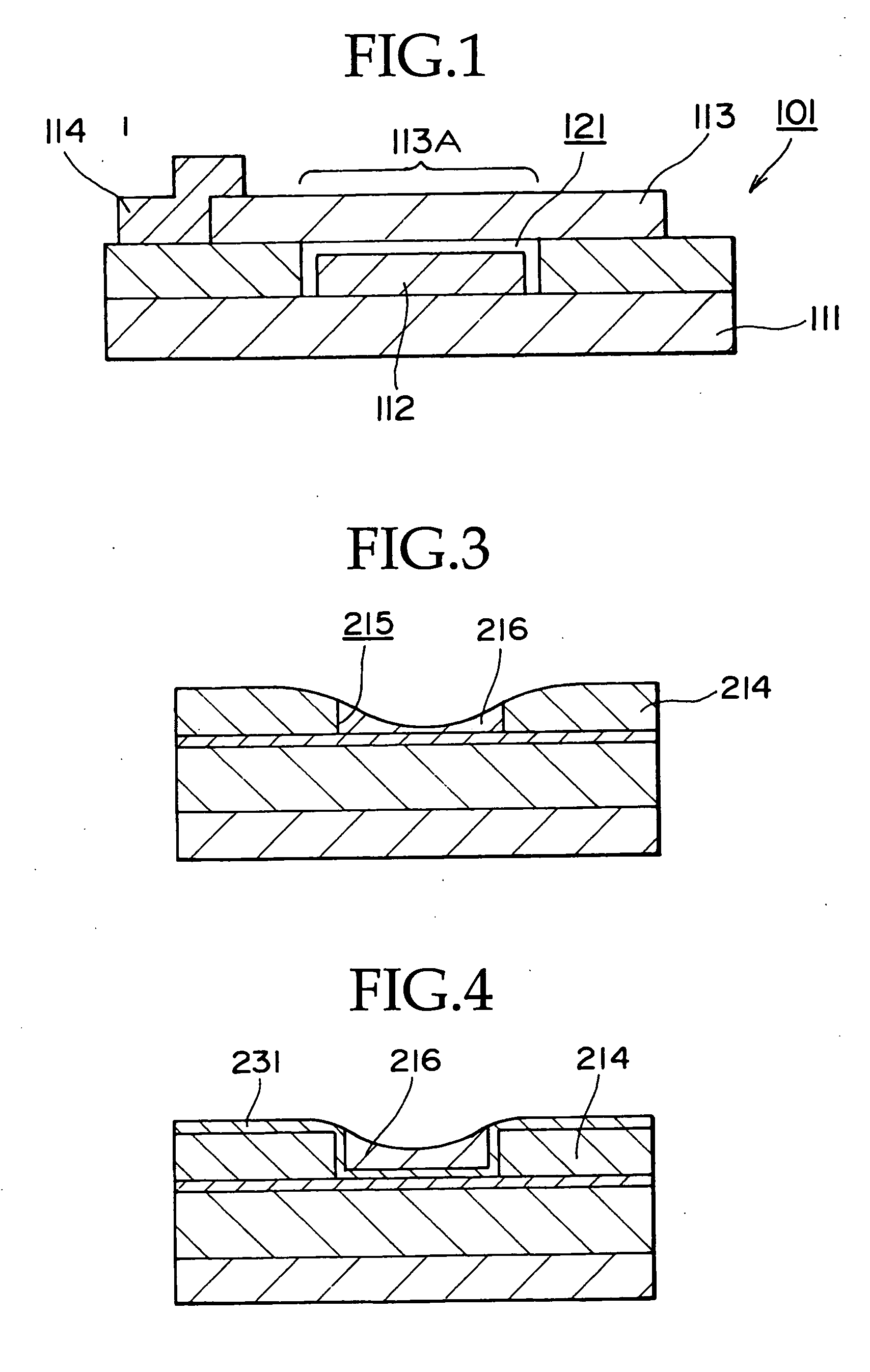
[0045] One embodiment of a micromachine production method according to the present invention is now described with reference to FIGS. 5A to 5J showing fabrication processes, respectively. FIGS. 5A to 5G and 5I are sectional views showing a schematic configuration, and FIGS. 5H and 5J are plan layout views, respectively.

[0046] As shown in FIG. 5A, a first insulating film 12 is formed on a silicon substrate 11. The first insulating film 12 is obtained by an arrangement of a silicon oxide film 121 and a silicon nitride film 122 that are layered in this order from the bottom, for instance. In this manner, a substrate 10 having, on a surface, the insulating film is fabricated. Next, a conductive film 13 that is to form a first electrode is formed on the first insulating film 12. The conductive film 13 is formed with a polysilicon film, for instance. The polysilicon film may be obtained with a conductive material contained at the time of film deposition or with the conductive material do...


PUM

PropertyMeasurementUnit
Thicknessaaaaaaaaaa
Thicknessaaaaaaaaaa
Densityaaaaaaaaaa

Abstract

In a production method of a micromachine having a space between first and second electrodes, a first electrode is formed on a substrate, and then a stopper film is formed on its surface. Next, a second insulating film is formed as to cover the stopper film. The thickness of the second insulating film is larger than a total thickness of the first electrode and stopper film. Then, second insulating film is polished. By this polishing, the stopper film is exposed to the outside to the outside, and is planarized. After forming an opening in the stopper film, a sacrifice film is burred in the opening. Surfaces of the sacrifice film and second insulating film are planarized, and a second electrode is formed on the second insulating film as to cross the sacrifice film. A space is formed between the first and second electrodes by removing the sacrifice film.

Description

BACKGROUND OF THE INVENTION [0001] 1. Field of the Invention [0002] The present invention relates to a micromachine production method, and more particularly, to a micromachine having a frequency filter function and being capable of integrating into a semiconductor device, and a production method thereof. [0003] 2. Description of the Related Art [0004] A microvibrator fabricated using a semiconductor process technology has features to ensure that an area occupied by each element is of small size, high quality factors (Q factors) are available and integration with other semiconductor devices is possible. Research organizations including University of Michigan have proposed to use the microvibrator as radio communication devices such as IF filters and RF filters, for instance. See Non-patent document 1, for instance. [0005] A conventional technology of a high frequency filter for radio communication is now described with reference to FIG. 1. As shown in FIG. 1, a microvibrator 101 has ...

Claims


Application Information

Patent Timeline
IPC IPC(8): B81B7/00B81B3/00B81C1/00H01L21/00H03H3/007H03H9/24H03J5/00
CPCB81B2201/0271H03H3/0072B81C2201/0125B81C1/00611B81B3/00B81B7/00
Inventor YAMAMOTO, YUICHI
Owner SONY CORP
Why Eureka
Try Eureka