Method for supplying gas while dividing to chamber from gas supply facility equipped with flow controller

a flow controller and gas supply technology, applied in the direction of liquid handling, packaged goods, instruments, etc., can solve the problems of increasing facility costs, inability to control the flow rate, and limited practical range of flow rate control

Active Publication Date: 2005-01-13
FUJIKIN INC +1
View PDF2 Cites 60 Cited by
  • Summary
  • Abstract
  • Description
  • Claims
  • Application Information

AI Technical Summary

Benefits of technology

[0021] The invention of claim 2 relates to a method of supplying divided gas to a chamber as claimed in claim 1, wherein said divided flow-rate control board FRC is equipped with a CPU, and is provided with a start and stop signal input terminal T2, an initial flow-rate ratio setting signal input terminal T3, a shower plate combination indicator signal input terminal T4, control flow rate signal output terminals T71 and T72 for the split pressure-type flow-rate controllers FV1 and FV2, and input/output abnormality alarm output terminals T91 and T92 for transmitting signals on the basis of the deviation between the flow-rate setting input signals and the control flow rate output signals for the split pressure-type flow controllers FV1 and FV2. With regard to different combinations of shower plates 3 and 4, the pressures P3′, P3″ of gas G flowing downstream of the control valves CV of the split pressure-type flow controllers FV1 and FV2 when the gas G totalling Q=Q1+Q2 G flows through the shower plates 3 and 4 respectively at the flow rate ratio Q1/Q2 are calculated from the aforementioned Q1=C1P3′ and Q2=C2P3″, with the flow rate ratio Q1/Q2 being a parameter for a plurality of total flow rates Q, and the initial flow-rate setting signal to the split pressure-type flow-rate controller FV1 having the greater flow-rate is an input signal voltage Vo for full opening of the control valve, while the initial flow-rate setting signal to the other split pressure-type flow-rate controller FV2 is the aforementioned P3″/P3′×Vo. Next, after an indicator signal corresponding to the combination of said shower plates 3 and 4 and the ratio P3′/P3″ between the initial flow-rate setting signals for said split pressure-type flow-rate controllers FV1 and FV2 have been inputted respectively to said input terminal T4 and the initial flow-rate ratio setting signal i

Problems solved by technology

Hence, it is a disadvantage of the pressure-type flow-rate control apparatus FCS that when the gas pressure P2 on the downstream side of the orifice rises greatly and disproportionately compared with the gas pressure P1 on the upstream side of the orifice, the critical expansion pressure condition is no longer satisfied, making it impossible to control the flow rate.
As a result, there is a problem in that the practical range for flow rate control is limited when the pressure P2 on the downstream side of the orifice increases.
As described above, it is noted that numerous problems arise in connection with gas flow rate control using a pressure-type flow-rate control sy

Method used


Image

  • Method for supplying gas while dividing to chamber from gas supply facility equipped with flow controller
  • Method for supplying gas while dividing to chamber from gas supply facility equipped with flow controller
  • Method for supplying gas while dividing to chamber from gas supply facility equipped with flow controller

Examples


Embodiment Construction

[0082] The following embodiment of the present invention is described with reference to the attached drawings hereunder.

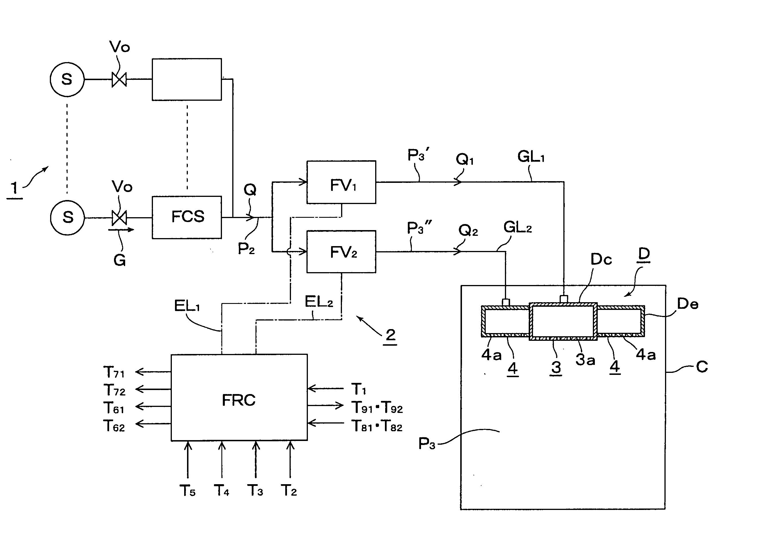
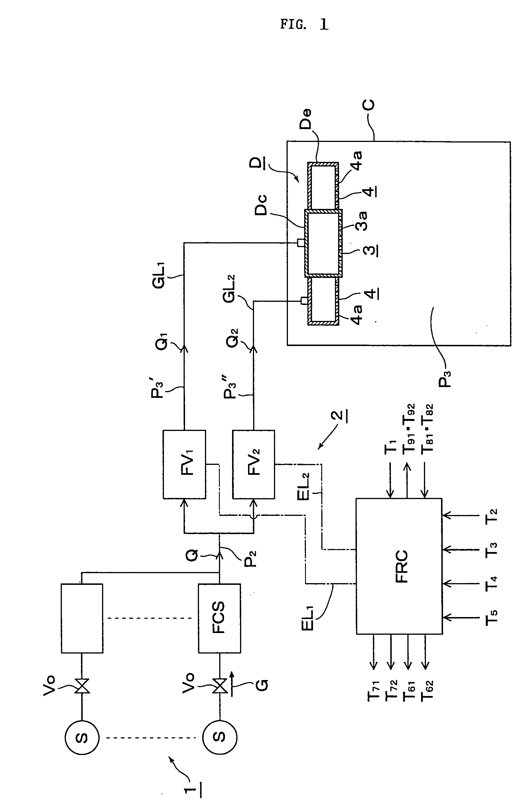
[0083]FIG. 1 is a complete diagrammatic view illustrating a method of supplying a divided gas to a chamber from a gas supply apparatus equipped with a flow-rate control system according to the present invention.

[0084] Referring to FIG. 1, a gas supply apparatus 1 comprises inter alia a supply source S of a treatment gas G, a gas main valve Vo, and a pressure-type flow-rate control system FCS.

[0085] A divided flow-rate control system 2 comprises inter alia split pressure-type flow-rate controllers FV1 and FV2, and a divided flow-rate control board FRC. Furthermore, referring to FIG. 1, C designates a chamber, D a gas discharger, Dc a centre part gas discharger, De an edge part gas discharger, GL1 a centre part split supply line, GL2 an edge part split supply line, Q the total gas flow rate, Q1 and Q2 the divided flow rates, P2 the pressure on the downstream side ...


PUM

PropertyMeasurementUnit
Fractionaaaaaaaaaa
Fractionaaaaaaaaaa
Fractionaaaaaaaaaa

Abstract

A method for supplying a specified quantity Q of processing gas while dividing at a desired flow rate ratio Q1/Q2 accurately and quickly from a gas supply facility equipped with a flow controller into a chamber. When a specified quantity Q of gas is supplied while being divided at a desired flow rate ratio Q1/Q2 from a gas supply facility equipped with a flow controller into a reduced pressure chamber C through a plurality of branch supply lines and shower plates fixed to the ends thereof, pressure type division quantity controllers FV1 and FV2 are provided in the plurality of branch supply lines GL1 and GL2. Opening control of both division quantity controllers FV1 and FV2 is started by an initial flow rate set signal from a division quantity control board FRC for fully opening the control valve CV of the pressure type division quantity controller having a higher flow rate and pressures P3′ and P3″ on the downstream side of the control valve CV are regulated thus supplying a total quantity Q=Q1+Q2 of gas while dividing into the chamber C through orifice holes (3a, 4a) made in shower plates (3, 4) at desired division quantities Q1 and Q2 represented by formulas Q1=C1P3′ and Q2=C2P3″ (where, C1 and C2 are constants dependent on the cross-sectional area of the orifice hole or the gas temperature on the upstream side thereof).

Description

FIELD OF THE INVENTION [0001] The present invention relates to an improved method of gas supply for supplying automatically divided gas to a chamber from a gas supply apparatus equipped with a pressure-type flow-rate control system for use in semiconductor manufacturing at semiconductor manufacturing facilities and the like. BACKGROUND OF THE INVENTION [0002] The so-called “pressure-type” flow-rate control system has been widely employed for the purpose of controlling the flow rate of gas to be supplied to semiconductor manufacturing facilities. [0003]FIG. 7 illustrates an example of a situation where a treatment gas G is supplied to a chamber C for forming silicone dioxide films by employing a pressure-type flow-rate control system FCS. The treatment gas G, which has a prescribed flow-rate Q, is supplied via the pressure-type flow-rate control system FCS into the chamber C at reduced pressure using a vacuum pump Vp, and is delivered at flow rate Q through a gas discharger D onto a ...

Claims


Application Information

Patent Timeline
IPC IPC(8): G05D7/06H01L21/205
CPCG05D7/0664Y10T137/7761Y10T137/7759G05D7/06
Inventor SUGIYAMA, KAZUHIKOIKEDA, NOBUKAZUNISHINO, KOUJIDOHI, RYOUSUKEUENOYAMA, TOYOMI
Owner FUJIKIN INC
Why Eureka
Try Eureka