Check patentability & draft patents in minutes with Patsnap Eureka AI!

Plastic card, plastic card producing method, hot press plate, and car producing device

Inactive Publication Date: 2005-01-13
SONY CORP
View PDF5 Cites 28 Cited by
  • Summary
  • Abstract
  • Description
  • Claims
  • Application Information

AI Technical Summary

Benefits of technology

[0030] In order to achieve the foregoing objects, a plastic card of the present invention is characterized by forming two or more reference holes in a plurality of corresponding positions in each sheet of a plurality of card component sheets, having a first positioning pin of substantially the same shape as said reference holes pass through at least one of said reference holes, having a second positioning pin of a smaller sectional area than the shape of said reference holes pass through at least one of the remaining reference holes, and performing welding while securing the positional relationship between said plurality of card component sheets.
[0031] The reference hole having substantially the same shape as the sectional shape of the first positioning pin (hereinafter referred to as a “first reference hole”) has the function of fixing (centering) and integrating a plurality of card component sheets. The reference hole having a greater hole area than the second positioning pin (hereinafter referred to as a “second reference hole”) has the function of adsorbing a lateral dislocation and extension of the sheets. Thereby, the respective card component sheets are integrated at high collation accuracy, without causing distortion and twisting of the sheets.
[0032] Thus, according to the present invention, plastic cards such as IC cards and the like can be manufactured by layering the card component sheets without substantially causing distortion and twisting of the card components sheets by an extremely simple method of adjusting the size of the second reference hole.

Problems solved by technology

Therefore there is the drawback of requiring a large-sized expensive collation facility.
As a result, the print pattern in the vicinity of the IC chip is remarkably disturbed and deformed, thereby causing the fatal drawback in appearance quality.
In this card, the distortion of the card surface in the vicinity of the IC chip may cause the fatal drawbacks on the leuco printing layer, such as character blur and missing of print character in write information, because a uniform gap with a thermal head for writing information is not assured.
The vacuum multistage press system requires much time for one cycle from degassing in the inside of the vacuum chamber to raising temperature and cooling of the press platen.
However, manufacture cycle time up to the completion of layer bonding of card component sheets is long, and therefore there are difficulties in maintaining productivity and mass production capability.
Further, there is also a problem that along with rapid heating and rapid cooling of the press platen, energy consumption becomes tremendous, thus being poor in economics.
In the meantime, in the layer bonding of various sheets of the IC card having the construction shown in FIG. 38, a lateral force is exerted during layering or heat press, and therefore a lateral dislocation occurs between adjacent sheets in a plurality of card component sheets, failing to perform accurate collation in some cases.
However, mutual fixing of the plurality of card component sheets with use of these positioning pins suffers from a problem that, if two positions of disposing the positioning pins are improper, the card component sheets cause distortion and twisting, and if heat press is performed in this state, print drift or the like occurs so that not only the appearance deteriorates but also the mechanical strength of the card degrades due to residual stress.
On the other hand, in the construction of the plate for heat press 80 described in Japanese Patent Unexamined Publication No. 2000-182014, the collation of the card component sheets C to be layered on the plate member 81b exclusively depends upon the repeat accuracy of sheet supply position available from the transfer mechanism 91, and it is therefore difficult to obtain high collation accuracy.
In general, as the sheet size increases, the collating operation between sheets becomes more difficult, and high collation accuracy is also required.
Hence, when trying to from high vacuum, the deformation of the aforesaid pressing surfaces becomes significant, thus failing to perform accurate heat press operation.
There is also a possibility that collation accuracy is disturbed due to the deformation of the pressing surface.
Further, there is a problem that in order to maintain the vacuum pressure of the inside of the plate for heat press 80, it is necessary to have the degassing hose 84 follow along with the transfer of the aforesaid plate 80, and therefore one is forced to accept limitations as to the degree of freedom of apparatus design.
Accordingly, to additions of the press sections such as to form the preheating press section in multi-stage, it fails to take a rapid measure, thereby making it very difficult to accurately manufacture a vast variety of plastic cards in accordance with the combination of card substrate component materials.

Method used


Image

  • Plastic card, plastic card producing method, hot press plate, and car producing device
  • Plastic card, plastic card producing method, hot press plate, and car producing device
  • Plastic card, plastic card producing method, hot press plate, and car producing device

Examples


first embodiment

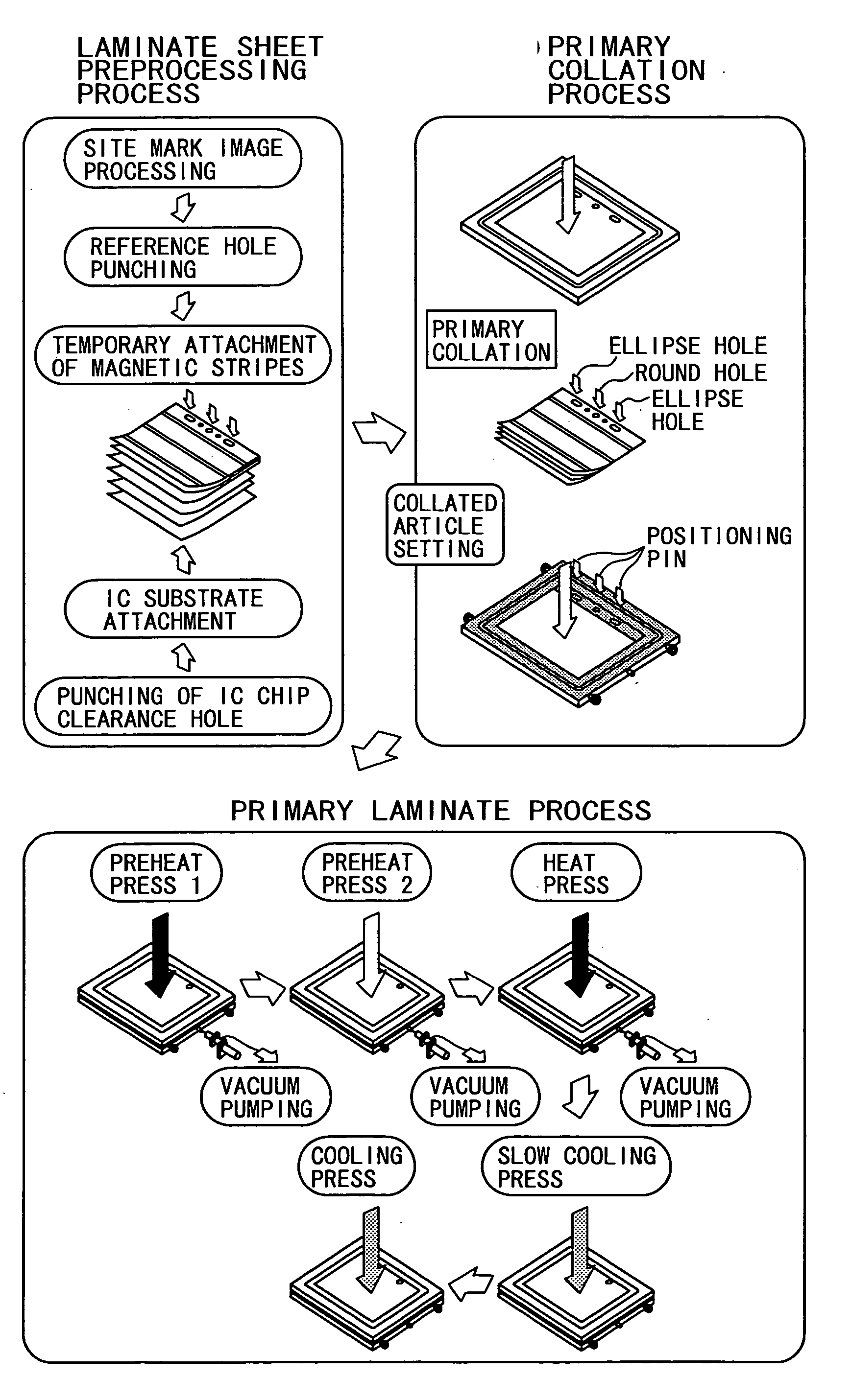
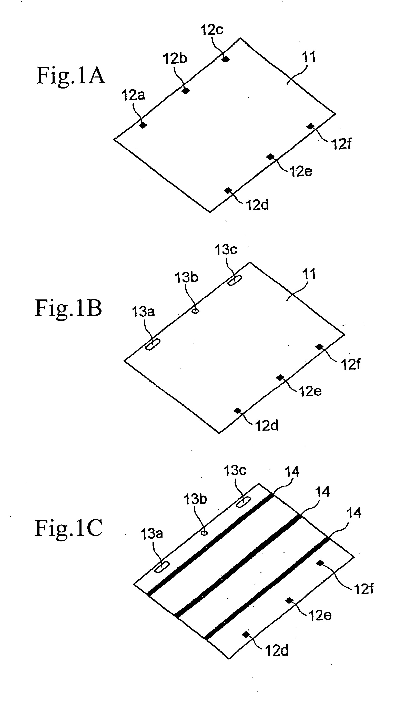
[0083]FIG. 1A is a perspective view showing one example of card component sheets prior to processing which constitutes a plastic card according to the present invention. FIG. 1B is a perspective view showing the state in which one round hole (a first reference hole) and two ellipse holes (second reference holes) are formed in the card component sheet of FIG. 1A. FIG. 1C is a perspective view showing the state in which three magnetic stripes are formed in the card component sheet of FIG. 1B.

[0084] As shown in FIG. 1A, a card component sheet 11 has a rectangular shape in which there are printed three along two longer-sides, or a total of six site marks 12a to-12f. Although the method of forming a plurality of reference holes in the card component sheet 11 is not particularly limited, three site marks 12a to 12c on the longer-side of the card component sheet 11 are read, and a round hole 13b is formed at the position of the site mark 12b being at the center of the three site marks, an...

second embodiment

[0116] A second embodiment of the present invention will be described hereinafter.

[0117] This embodiment describes a card manufacturing apparatus for implementing the heat press process described in the first embodiment and a specific example of plates for heat press used for this apparatus.

[0118]

[0119]FIG. 15 is a perspective view showing schematically the whole of a card manufacturing apparatus applied to this embodiment.

[0120] A card manufacturing apparatus 100 is a secondary apparatus for welding to integrate rectangular various card component sheets (hereinafter generally referred to as a “card component sheet C”) of multi-leaves size (about A4 size) corresponding to nine pieces of non-contact type IC cards as described with reference to FIG. 38.

[0121] The card manufacturing apparatus 100 has a plurality of stations for performing a variety of processing while circulating, between two stages of upper and lower transfer paths, a carrier plate (plate for heat press) 101 consi...

third embodiment

[0269]FIG. 32 to FIG. 36E show a third embodiment of the present invention.

[0270] In the third embodiment, the construction of a pair of upper and lower plate members forming a carrier plate as a plate for heat press is different from the above-mentioned second embodiment.

[0271]FIG. 32 is a plan view of an upper plate member 211 in the third embodiment, viewed from its pressing surface side. FIG. 33 is a plan view of a lower plate member 212 in the third embodiment, viewed from its pressing surface side.

[0272] The upper plate member 211 is of a rectangular shape and made of a metal material such as aluminum alloy, and to the pressing surface thereof, a mirror finished surface plate 211a that is for example made of stainless steel is fixed via vises 211b.

[0273] Clearance holes 211c are formed in an in-plane region of the mirror finished surface plate 211a so as to correspond to the vertically disposing positions of the positioning pins 215 of the lower plate member 212. Additiona...


PUM

PropertyMeasurementUnit
Thicknessaaaaaaaaaa
Forceaaaaaaaaaa
Shapeaaaaaaaaaa

Abstract

Collation and welding of card component sheets can be performed in a simple facility. Plastic cards such as IC cards having substantially no distortion and twisting are provided. A round hole (17) and an ellipse hole (18) are formed at the corresponding positions in layered component sheets (19a to 19d), and positioning pins (21) are inserted and passed through respective holes. Since at this occasion, the ellipse hole (18) has play relative to the positioning pin (21), the distortion and twisting of each card component sheet can be adsorbed, and the appearance can be improved by avoiding printing dislocation and the like. It is also able to prevent mechanical strength from lowering due to residual stress.

Description

TECHNICAL FIELD [0001] The present invention relates to a plastic card in which a plurality of card component sheets forming a plastic card such as an IC card is layered without causing dislocation in collation, also to a plastic card manufacturing method, a plate for heat press and a card manufacturing apparatus. BACKGROUND ART [0002] Recently, in card-like storage media such as credit cards, ID cards and cash cards, there has been development in, in addition to magnetic cards, IC cards mounting an IC module that contains in the card material semiconductor memory such as microprocessors, RAM (random access memory), ROM (read only memory) and the like. As this type of IC card, there are for example contact type IC cards, non-contact type IC cards, and IC cards having both functions of contact and non-contact type IC cards. Any of these IC cards is superior to other card-like storage medium in the point of having extremely large amount of information storage and having security prope...

Claims


Application Information

Patent Timeline
IPC IPC(8): B29C65/00B29C65/18B29C65/78B29L7/00B29L9/00B32B37/08B32B37/18B32B38/00B32B38/16B42D15/10G06K19/077
CPCB29C65/7808B42D25/00B29C66/00441B29C66/81455B29C66/8163B29C66/82661B29L2009/00B29L2017/00B32B37/0015B32B37/08B32B37/182B32B38/0036B32B38/162B32B38/18B32B38/1841B32B2038/047B32B2425/00B32B2429/00G06K19/077G06K19/07722B42D25/40B29C65/7861B29K2995/007B29C66/81264B29C66/433B29C66/45B29C66/71B29C66/1122B29C66/0242B42D25/305B42D25/455B42D25/46B42D25/47B42D25/475B42D25/369B29K2077/00B29K2069/00B29K2067/006B29K2067/003B29K2067/00B29K2055/02B29K2033/12B29K2025/08B29K2025/06B29K2001/14B29K2001/08B42D25/373
Inventor KANO, KENICHINISHIMURA, KIMITAKA
Owner SONY CORP
Features
  • R&D
  • Intellectual Property
  • Life Sciences
  • Materials
  • Tech Scout
  • Unparalleled Data Quality
  • Higher Quality Content
  • 60% Fewer Hallucinations
Learn More