
Drive device

a technology of drive device and cooling liquid, which is applied in the direction of magnetic circuit rotating parts, electric propulsion mounting, magnetic circuit shape/form/construction, etc., can solve the problems of ineffective cooling of inverter components by cooling liquid, inefficient cooling efficiency, and inefficient cooling technique, so as to efficiently cool electric motors and inverters, the effect of minimizing the amount of refrigeran

Inactive Publication Date: 2005-01-13
AISIN AW CO LTD
View PDF10 Cites 60 Cited by
  • Summary
  • Abstract
  • Description
  • Claims
  • Application Information

AI Technical Summary

Benefits of technology

[0011] The invention thus provides, among other things, an apparatus and a method that efficiently cools an electric motor and an inverter while minimizing the amount of refrigerant that is used according to heat-resistant temperatures thereof in a drive unit, in which the inverter is united with the electric motor. The electric motor and inverter are cooled by creating a temperature difference between a refrigerant that cools the electric motor and a refrigerant that cools the inverter while cutting off thermal conduction from the electric motor to the inverter with the use of the refrigerant.

Problems solved by technology

However, effective cooling of the inverter component by the cooling liquid is not expected.
With this technique, since a tip end of a wall that defines the spiral passage on the cylindrical-shaped inner body contacts directly with the jacket, heat transfer to a saddle portion that defines a cooling space for the inverter component is thought to increase, which is not efficient in terms of cooling efficiency.
However, since a layer of thermal insulation constituted by the cooling liquid contacts with both the motor body and the heat sink, a cooling liquid circulating system of a large capacity is required to lower the temperature of the cooling liquid to the heat-resistant temperature of the controller in order to protect the controller, in which case the technique is not efficient in terms of cooling efficiency.

Method used


Image

  • Drive device
  • Drive device
  • Drive device

Examples


first embodiment

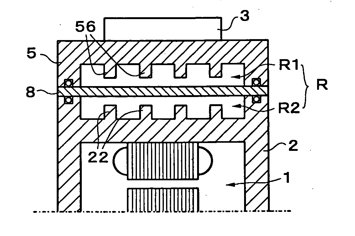
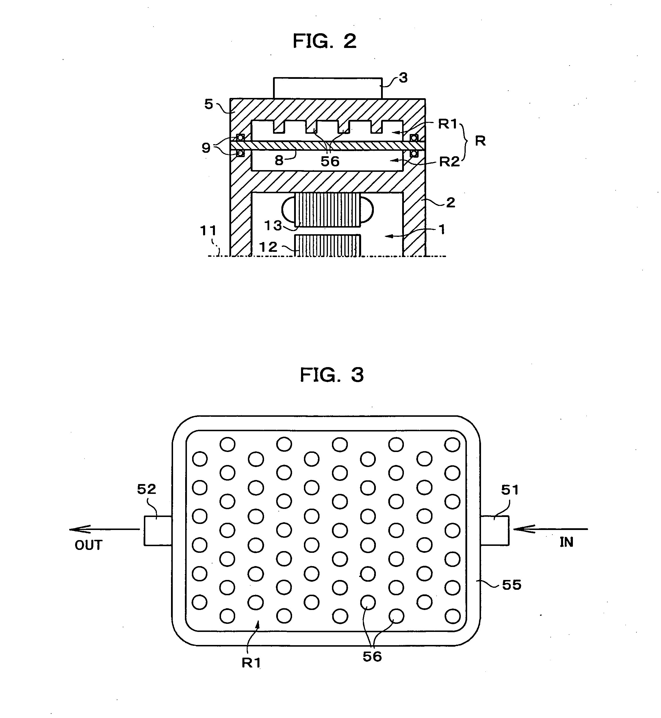
[0026] Subsequently, FIG. 2 schematically shows a longitudinal cross sectional view, in an axial direction, of the drive unit according to a Reference numeral 1 denotes the electric motor, 11 a rotor shaft of the motor, 12 a rotor core, and 13 a stator core. As shown in the figure, a space R defined in a region, in which the heat sink 5 is opposed to the drive unit casing 2, is compartmented by a separator 8 into a first chamber R1 facing the heat sink and a second chamber R2 facing the drive unit casing 2, and is communicated to the flow passage of the refrigerant as described above. The heat sink 5 comprises a multiplicity of heat-sink side fins 56 extending into the first chamber R1 to ensure a heat exchange area and disposed apart from the separator 8. In addition, the respective fins 56 are shown, in all the drawings, as being enlarged and exaggerated in dimension relative to the space R and the number of the fins as shown is less than the number of fins actually arranged for ...

third embodiment

[0043] Both of the two embodiments described above make exclusive use of a refrigerant as a layer of thermal insulation without taking account of the heat conductive property of the separator 8. When a low thermal conductive member 6 made of a material of low thermal conductivity, that is, a thermal insulating material is used for the separator 8 or a low thermal conductive member, such as film-shaped member or the like, made of a material of low thermal conductivity is provided along and arranged on a member of a metallic material, that comprises the separator 8 as a backing, at least drive-unit-side fins 22 can be configured to contact directly with a low thermal conductive member 6 that constitutes the separator 8, or a member provided along the low thermal conductive member. Next, a third embodiment shown in FIG. 10 adopts such a construction. In addition, the low thermal conductive member 6 referred herein to does not necessarily mean a member made of a single material but incl...


PUM


Abstract

A drive unit comprises an electric motor, a drive unit casing 2 accommodating therein the electric motor, an inverter 3 that controls the electric motor, and a flow passage of a refrigerant that cools the inverter. The inverter defines a space R between it and a heat sink 5 integral with a substrate of the inverter, and is mounted to the drive unit casing, the space is compartmented by separation means 8 into a first chamber R1 facing the heat sink and a second chamber R2 facing the drive unit casing, and is communicated to the flow passage of the refrigerant, and the heat sink comprises heat-sink-side fins 56 extending into the first chamber and apart from the separation means. Thereby, temperature gradient can be provided between the both chambers, and effective cooling of the heat sink and the drive unit casing can be made possible with less flow rate of the refrigerant as compared with the case where the entire space comprising a single layer is cooled by the refrigerant according to the heat-resistant temperature of the inverter.

Description

INCORPORATION BY REFERENCE [0001] This application claims priority from Japanese Patent Application No. 2002-269232, filed Sep. 13, 2002 through International Application No. PCT / JP03 / 05749, filed May 8, 2003, the disclosures of which are incorporated by reference thereto. BACKGROUND OF THE INVENTION [0002] 1. Field of the Invention [0003] The invention relates to a cooling technique in drive units for electric cars and drive units for hybrid cars. [0004] 2. Description of Related Art [0005] When an electric motor is used as a power source for vehicles, the electric motor needs a control device (an inverter in the case of an AC electric motor) that controls the electric motor. Since the control device, for example, the inverter, is connected to the electric motor by way of a power cable, the control device can be arranged in an appropriate position apart from the electric motor. For the convenience of a car-mounted arrangement, it is desired that the control device be united with th...

Claims


Application Information

Patent Timeline
IPC IPC(8): B60K1/00B60K6/26H02K5/20H02K9/19H02K11/04H05K7/14H05K7/20
CPCB60K1/00B60K6/26B60K2001/003H05K7/20927H02K9/19H02K11/0073H02K5/20H02K11/33H02K5/203H02K9/22B60K11/02H02K5/18
Inventor TAKENAKA, MASAYUKIKUTSUNA, NARUHIKOYAMAGUCHI, KOZO
Owner AISIN AW CO LTD
Features
  • Generate Ideas
  • Intellectual Property
  • Life Sciences
  • Materials
  • Tech Scout
  • Unparalleled Data Quality
  • Higher Quality Content
  • 60% Fewer Hallucinations
Learn More