Structure of the stem of LED chip unit bulb

a technology of led chip and bulb stem, which is applied in the direction of discharge tube luminescnet screen, semiconductor devices for light sources, lighting and heating apparatus, etc., can solve the problems achieve the effect of prolonging the life of the bulb, facilitating efficient circulation and heat absorption

Inactive Publication Date: 2005-01-13
LEE HAN MING
View PDF5 Cites 29 Cited by
  • Summary
  • Abstract
  • Description
  • Claims
  • Application Information

AI Technical Summary

Benefits of technology

[0004] Another purpose of the present invention is to provide a new structure of the stem of LED chip unit bulb, wherein the gradient of the arc-shaped, circular wall of the disk enables the chip to generate light that refracts at different angles, giving rise to a wide-angle, open, homogeneous light source.
[0005] An additional purpose of the present invention is to provide a new structure of the stem of LED chip unit bulb, wherein the vacuum inside the bulb facilitates efficient circulation and therefore heat absorption. As a result, despite the heat dissipation of the chip, the temperature of the bulb does not increase, prolonging the life of the bulb.

Problems solved by technology

As a result, despite the heat dissipation of the chip, the temperature of the bulb does not increase, prolonging the life of the bulb.

Method used


Image

  • Structure of the stem of LED chip unit bulb
  • Structure of the stem of LED chip unit bulb
  • Structure of the stem of LED chip unit bulb

Examples


Embodiment Construction

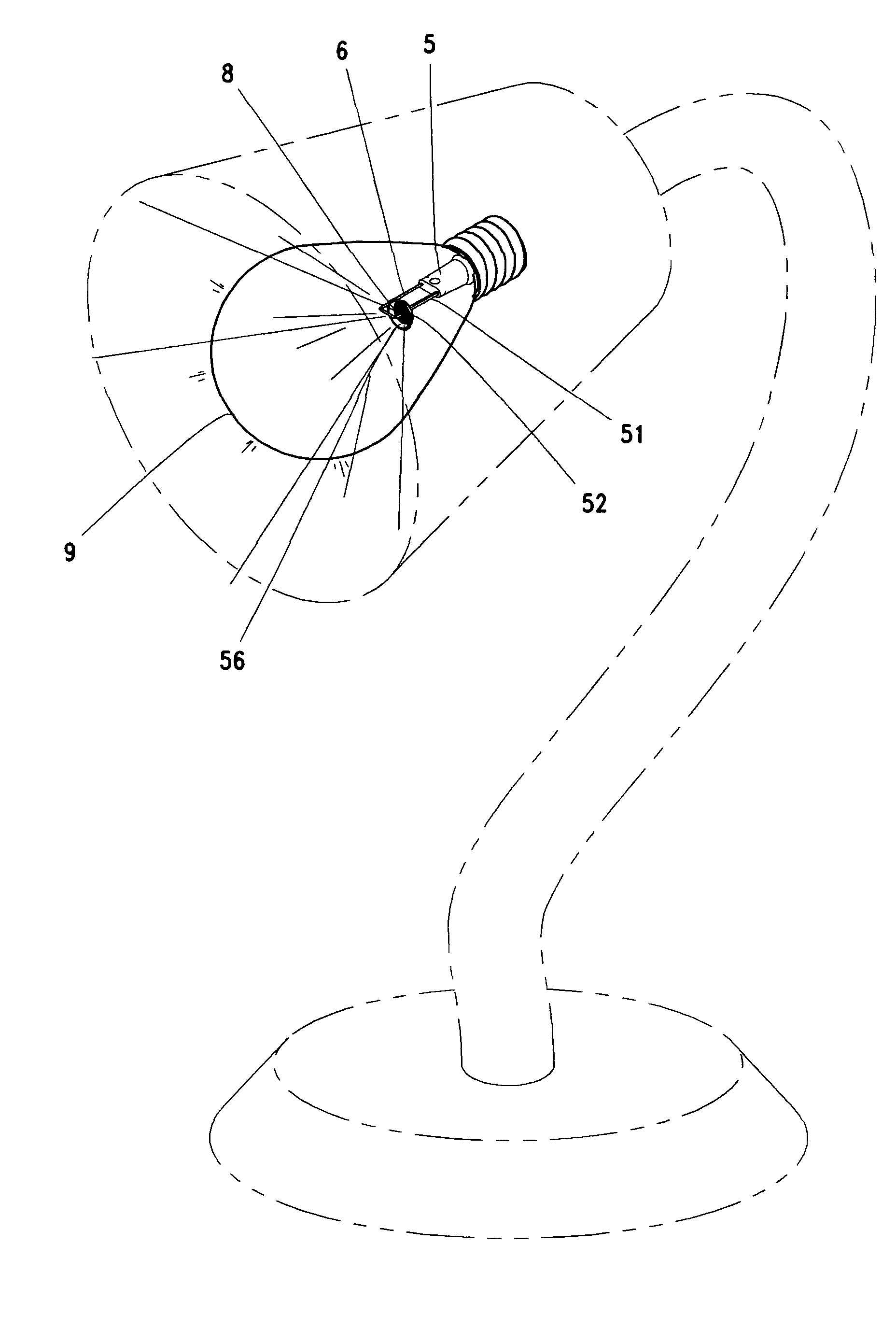
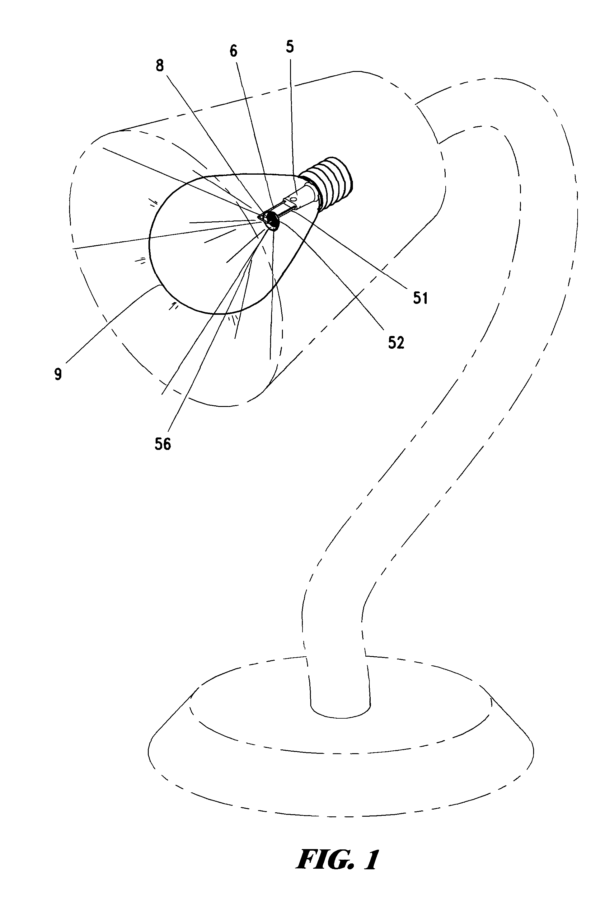
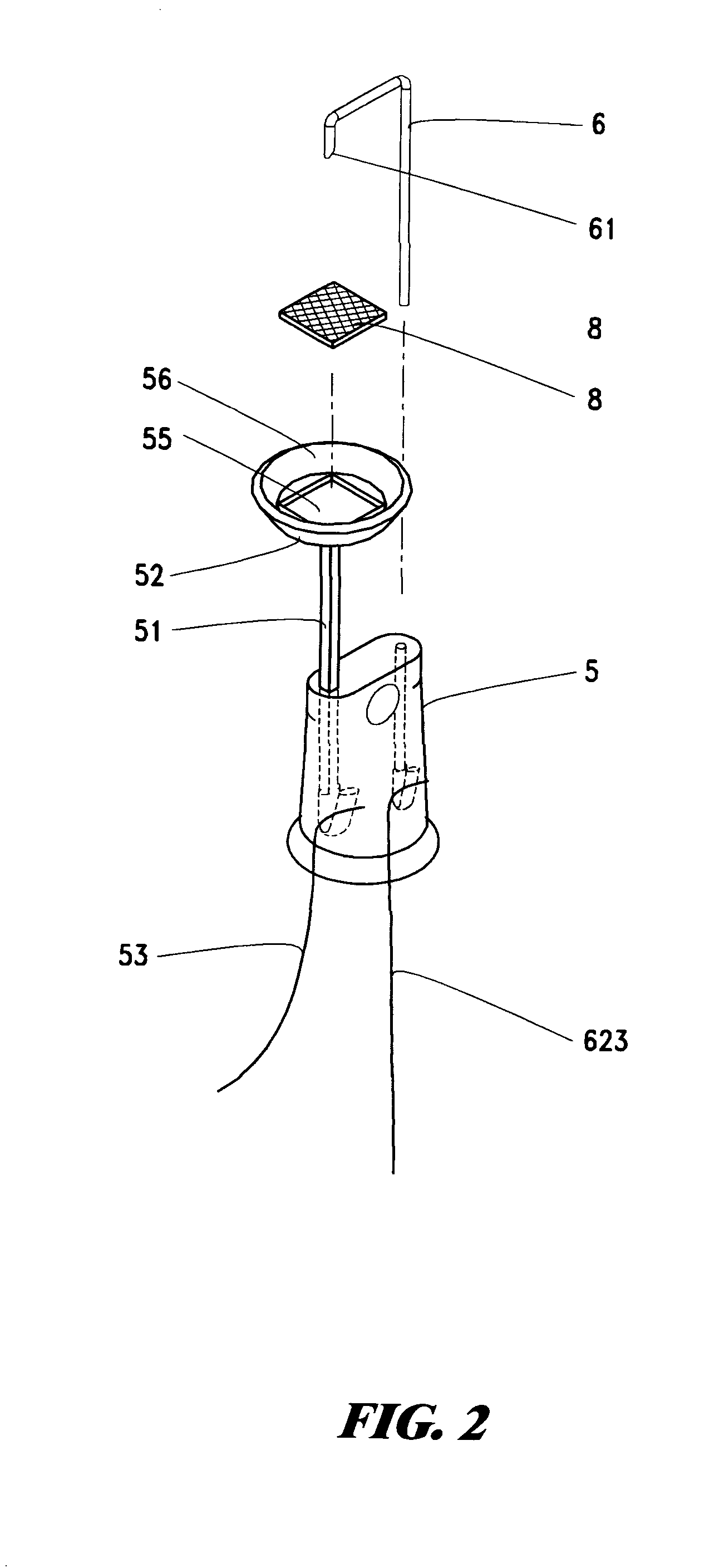
[0011] As shown in FIGS. 1-5, the present invention is about the new structure of the stem of LED chip unit bulb that comprise a cup disk, a chip, a stand, a molybdenum alloy wire and a stem. Essentially, the stem 5 condenses and connects the upper end of the support 51 and the supportive chip unit disk 52. The lower end of the stand presses against the rivet 53 so that it extends beyond the stem body to be connected to the cathode power. The center of the disk is concave so as to form a holding chamber 55 whose inner diameter is open, arc-shaped and circular. The arc-shaped slope 56 of the inner circumference of the disk has circular groove pointing toward the upward, open cathode disk. The stem support is equipped with a molybdenum alloy wire 6 whose end is tapered off to form the tip 61, taking a 180° turn at an appropriate location, so that the tip hooks and presses against the surface of chip 8 and therefore enables electric conduction. The lower end of the molybdenum alloy wir...


PUM


Abstract

The present invention is related to a new structure of the stem of LED Chip Unit bulb, which comprises a cup disk, a chip, a stand, a molybdenum alloy wire and a stem. Essentially, the brace-end of the stem is connected to a supportive chip cup disk. The center of the disk is concave so as to form a holding chamber whose inner diameter is open, arc-shaped and circular. The molybdenum alloy wire is tapered off to a point and thus it takes a turn of 180°, hooking and pressing against the chip. Given the elastic coefficient of the barb-turning angle, the tip of the molybdenum alloy wire may point-press against the chip in a normal state in response to the temperature-dependent expansion-contraction feature of the chip. The gradient of the arc-shaped, circular wall of the disk enables the chip to generate light that refracts at different angles, giving rise to a wide-angle, open, homogeneous light source. The vacuum inside the bulb facilitates efficient circulation and therefore heat absorption. As a result, despite the heat dissipation of the chip, the temperature of the bulb does not increase, prolonging the life of the bulb. Hence, the new structure of the stem of LED chip unit bulb does have a practical utility.

Description

BACKGROUND OF THE INVENTION [0001] With regard to a conventional bulb, the stem supports the tungsten filament. The stems have to be manufactured in the following way. Parts like inner tubes, trumpet tubes, inner stems and guiding filaments are processed one by one to produce semi-finished products. Then, tungsten filaments are pressed. Finally, all the parts and the shell of the bulb are sealed by fusion and condensation. The manufacturing process is labor-intensive and it is carried out by more than one workstation. Accordingly, not only is throughput unsatisfactory, but quality control also is seldom easy, leading to a rather high defect rate. Hence, the cost efficiency is low and the contemporary economic requirements are not met. On the other hand, all the aforesaid parts together occupy considerable space of the bulb. Since the glass components contain lead, the illumination of the bulb brings about the evaporation of lead, increasing the temperature of the bulb and therefore ...

Claims


Application Information

Patent Timeline
Patent Type & Authority Applications(United States)
IPC IPC(8): F21K99/00H01J1/62H01L33/48H01L33/62
CPCF21K9/135F21Y2101/02H01L33/483F21V29/58H01L2924/0002H01L33/62H01L2924/00F21K9/232F21Y2115/10
Inventor LEE, HAN-MING
Owner LEE HAN MING
Why Eureka
Try Eureka