
Method and system for producing a drive signal for a current steering amplifier

a current steering amplifier and drive signal technology, applied in the direction of low noise amplifiers, amplification control details, gain control, etc., can solve the problems of significantly degrading significantly degrading the performance of the associated tuner, and affecting the overall performance of the tuner, so as to achieve low noise amplification, improve linearity and gain performance characteristics, and automatic gain control

Inactive Publication Date: 2005-01-13
AVAGO TECH INT SALES PTE LTD
View PDF3 Cites 3 Cited by
  • Summary
  • Abstract
  • Description
  • Claims
  • Application Information

AI Technical Summary

Benefits of technology

The present invention is a method and apparatus for amplifying signals in a cable television system. The invention includes a differential amplifier drive signal that adjusts the negative and positive components of the differential control signal to match the supply voltage signal. The invention also includes a gain control device that detects the signal level of each amplified signal and adjusts the gain of the second amplification module accordingly. The invention has the advantage of improving second and third order distortion product performance by using a differential circuit topology and facilitating full use of the cable signal range with little or no noise figure penalty while also reducing space requirements, costs, and easing the manufacturability cable set-top boxes. The invention also includes techniques for autonomous local AGC of variable gain type amplifiers, current steering circuits, and providing signals proportional to amplifier gains that are scalable to accommodate different numbers of multiple tuner applications without creating a significant impact on broadband bandwidth. The invention combines high linearity and low noise in a distribution amplifier for multiple tuner applications with a large variable gain range.

Problems solved by technology

Due to the complexity and availability of entertainment program source material, multiple television tuners are included in most set-top cable boxes and cable modems.
These additional features, material, and functionality cause the set-top boxes to be significantly more complex and include increased functionality.
Unfortunately, however, the use of the passive splitters degrades the overall performance of the tuner.
For example, passive splitters are known to create insertion losses of about 6 dB, which significantly degrades the performance of the associated tuners.
This level of degradation, in turn, impacts the overall system's noise figure and signal-to-noise ratio (SNR).
An additional drawback of passive splitters in cable set-top boxes is that they do not permit the full use of cable signal ranges.

Method used


Image

  • Method and system for producing a drive signal for a current steering amplifier
  • Method and system for producing a drive signal for a current steering amplifier
  • Method and system for producing a drive signal for a current steering amplifier

Examples


Embodiment Construction

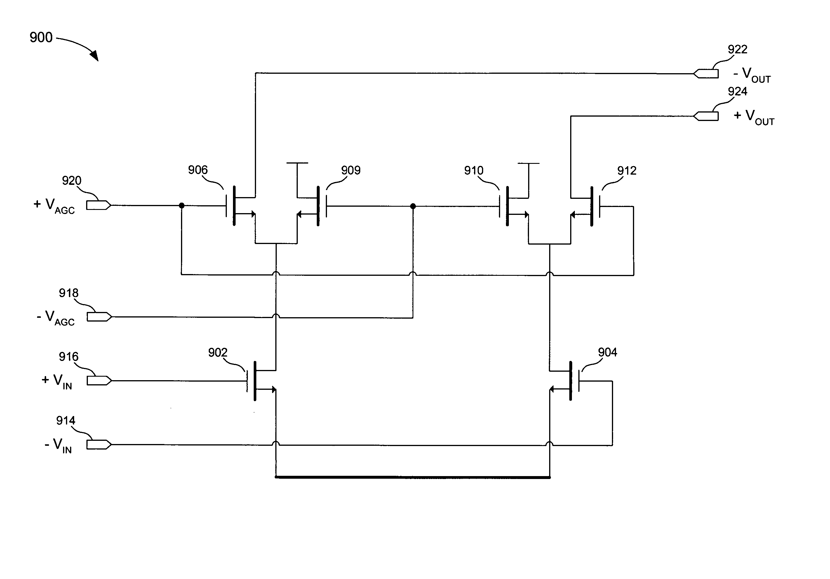
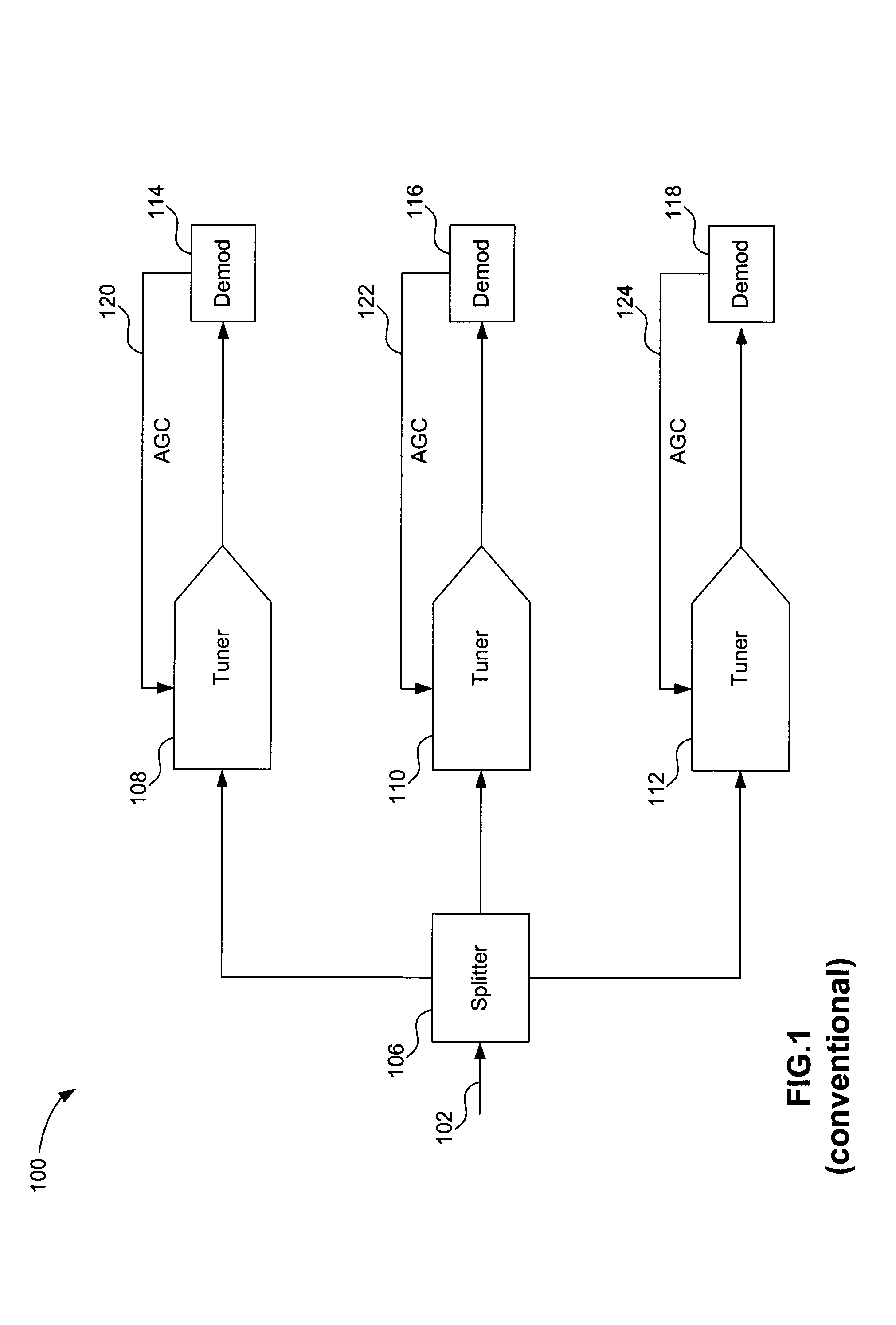
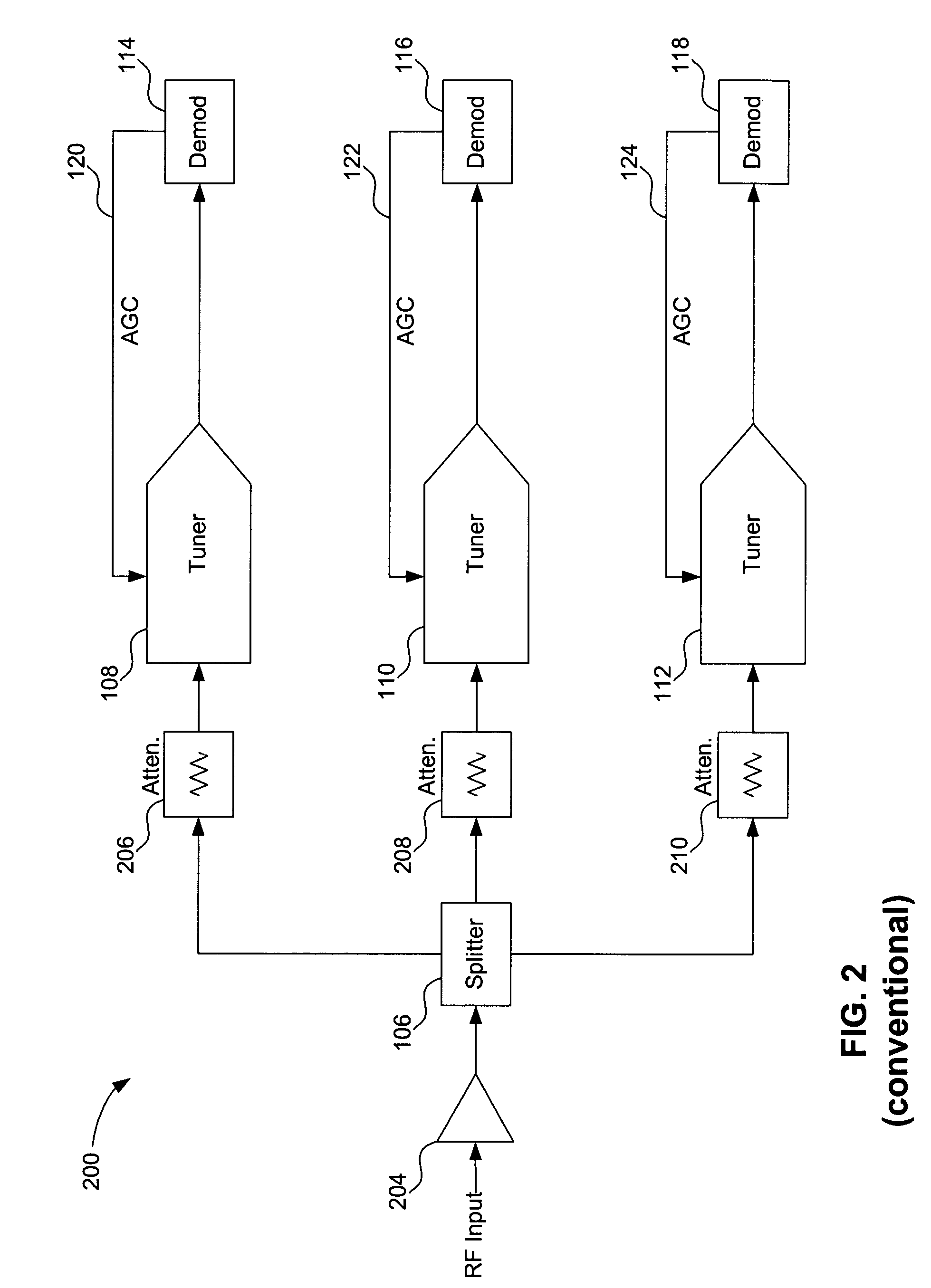
[0038] The following detailed description of the present invention refers to the accompanying drawings that illustrate exemplary embodiments consistent with this invention. Other embodiments are possible, and modifications may be made to the embodiments within the spirit and scope of the invention. Therefore, the following detailed description is not meant to limit the invention. Rather, the scope of the invention is defined by the appended claims.

[0039] It would be apparent to one of skill in the art that the present invention, as described below, may be implemented in many different embodiments of hardware, software, firmware, and / or the entities illustrated in the figures. Any actual software code with the specialized controlled hardware to implement the present invention is not limiting of the present invention. Thus, the operation and behavior of the present invention will be described with the understanding that modifications and variations of the embodiments are possible, gi...


PUM


Abstract

Provided is a method and system for producing a drive signal for a current steering amplifier. An exemplary method comprises receiving a supply voltage signal and a differential input signal as a circuit input. A differential amplifier drive signal is produced in response to the received supply voltage signal, the received differential input signal, and the received differential control signal. The received differential input signal is adjusted to a value where magnitudes of negative and positive components of the differential control signal become equal to one another and are within a predetermined amount of a magnitude of the supply voltage signal.

Description

CROSS-REFERENCE TO RELATED APPLICATIONS [0001] This application is a continuation of the U.S. Non-Provisional Application entitled “Method and System for Producing a Drive Signal for a Current Steering Amplifier,” Ser. No. 10 / 429,700, filed May 6, 2003, which is a continuation of U.S. Non-Provisional Application entitled “Method and System for Producing a Drive Signal for a Current Steering Amplifier,” Ser. No. 10 / 214,091, filed Aug. 8, 2002, which claims the benefit of U.S. Provisional Application No. 60 / 363,545, filed Mar. 13, 2002, and U.S. Provisional Application No. 60 / 312,086, filed Aug. 15, 2001, all of which are incorporated herein by reference.BACKGROUND OF THE INVENTION [0002] 1. Field of the Invention [0003] The present invention relates generally to the field of low noise amplifiers (LNAs) used in tuners. More specifically, the present invention relates to LNAs used in the tuners of set-top boxes, cable modems, and high definition television (HDTV) devices. Tuners of thi...

Claims


Application Information

Patent Timeline
Patent Type & Authority Applications(United States)
IPC IPC(8): H03F3/45H03G1/00H03G3/30
CPCH03F3/45183H03F3/45201H03F3/45475H03F2200/294H03F2200/372H03F2203/45302H03G3/3052H03F2203/45464H03F2203/45466H03F2203/45638H03F2203/45696H03G1/0029H03G3/3036H03F2203/45311
Inventor FANOUS, ADELDAUPHINEE, LEONARDBURNS, LAWRENCE M.MCMULLIN, DONALD
Owner AVAGO TECH INT SALES PTE LTD
Learn More