Transmission spectrometer with improved spectral and temperature characteristics

a technology of transmission spectrometer and temperature characteristics, applied in the field of optical systems, can solve the problems of light propagation within the spectrometer, incident on the detector, diffraction element, warp or stretch, etc., and achieve the effect of reducing the effect of reflective diffracted ligh

Active Publication Date: 2005-01-13
IBSEN PHOTONICS
View PDF13 Cites 26 Cited by
  • Summary
  • Abstract
  • Description
  • Claims
  • Application Information

AI Technical Summary

Benefits of technology

[0005] One type of scattered light that it is particularly important to reduce is light that is scattered within the spectrometer from the diffraction element. For a transmissive diffracting element, such as a diffraction grating, a portion of the incident light is reflectively diffracted. This light may propagate within the spectrometer and be incident on the detector if not properly controlled. One approach to reducing the effect of reflectively diffracted light in the spectrometer is to orient the diffraction grating so that the light is reflected out of the plane of the detected light.
[0006] Another aspect of good performance of a transmission spectrometer is that it behaves uniformly over a range of temperatures. The diffraction element, when attached to a frame, often warps or stretches when the temperature changes. This results in a shift and / or defocusing of the light at the detector, thus leading to a degradation of the spectral performance of the spectrometer. One approach to reduce the grating's temperature-dependent behavior is to mount it in a manner that permits independent thermal expansion and contraction of the grating and the frame when the temperature changes. This reduces the temperature-related stresses that occur when the temperature changes, and so the associated drift with temperature is reduced. As a result, the temperature range over which the spectrometer can operate with high accuracy is increased.

Problems solved by technology

This light may propagate within the spectrometer and be incident on the detector if not properly controlled.
The diffraction element, when attached to a frame, often warps or stretches when the temperature changes.
This results in a shift and / or defocusing of the light at the detector, thus leading to a degradation of the spectral performance of the spectrometer.

Method used


Image

  • Transmission spectrometer with improved spectral and temperature characteristics
  • Transmission spectrometer with improved spectral and temperature characteristics
  • Transmission spectrometer with improved spectral and temperature characteristics

Examples


Embodiment Construction

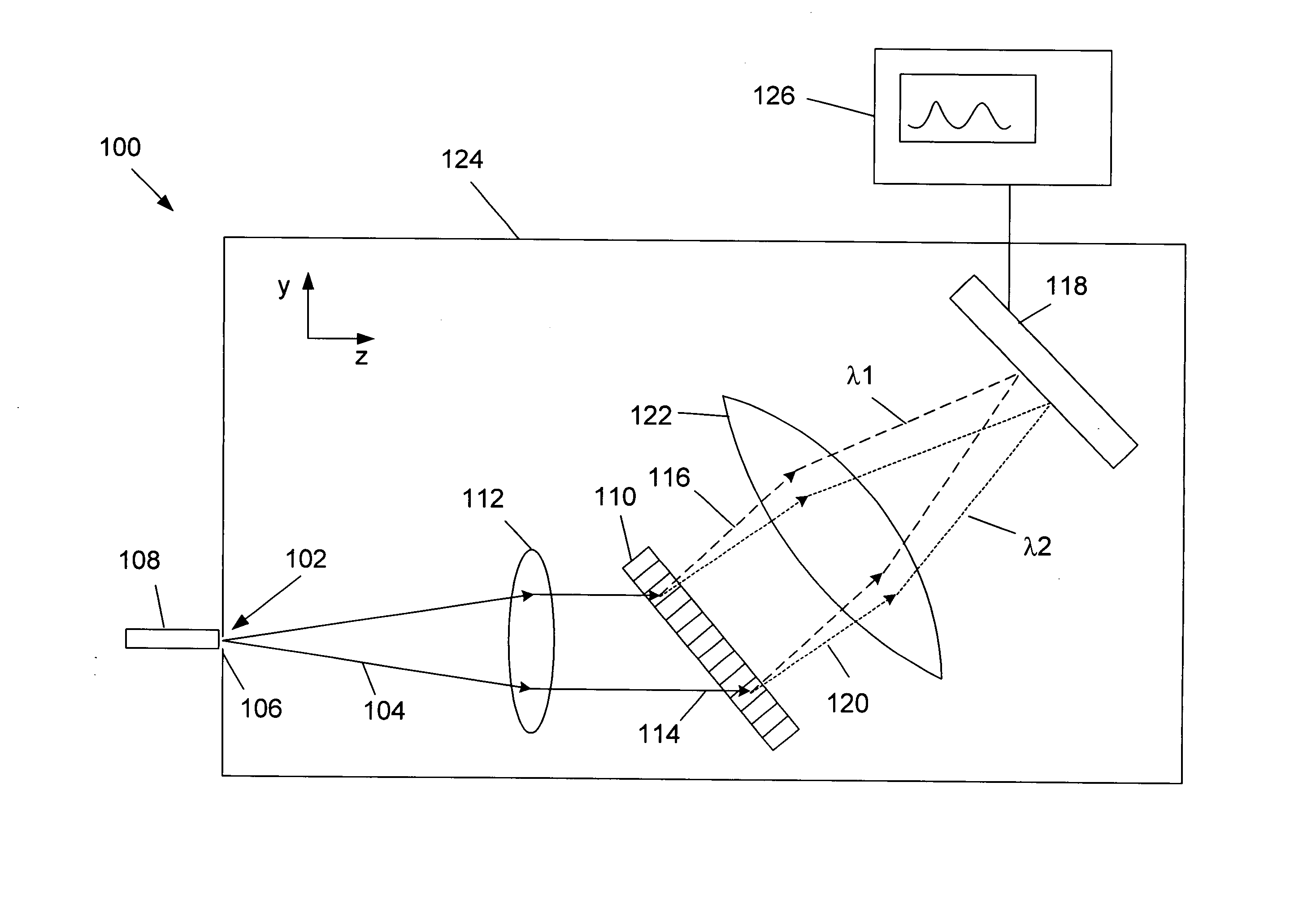
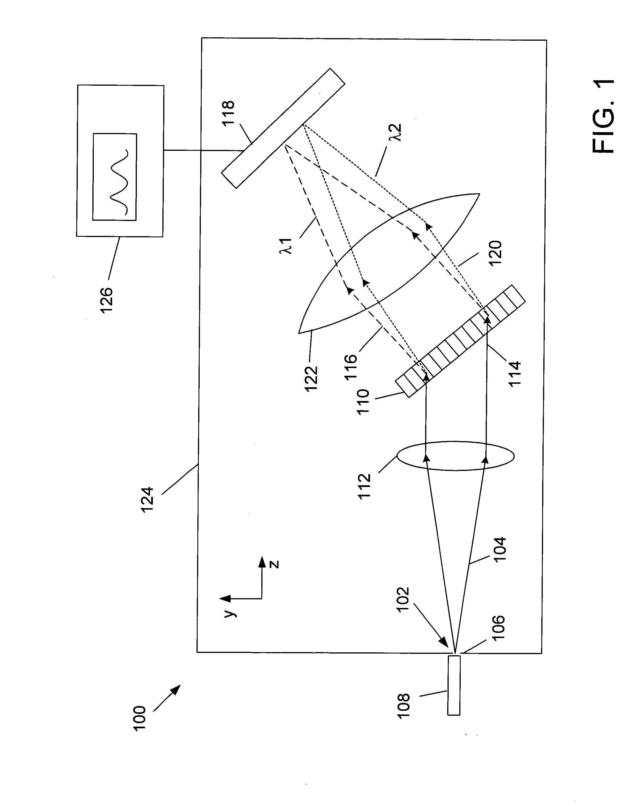
[0027] An embodiment of a spectrometer 100 is schematically illustrated in FIG. 1. The spectrometer 100 has an input port 102 through which light 104 is introduced to the spectrometer 100. The input port 102 may include a slit 106, or an optical fiber 108, or a combination of both. An important function of the input port 102 is to provide some spatial restriction to the light 104 entering the spectrometer 100 so as to increase the resolution at the detector, since the input port 102 is typically imaged to the detector.

[0028] The light 104 passes from the input port 102 to a transmissive diffraction element 110, for example a diffraction grating. The divergence of the light 104 may be reduced by a first collimating unit 112. The first collimating unit 112 may comprise one or more lenses in combination. The first collimating unit 112 may collimate the light 104 so that the light 114 incident on the grating 110 is parallel. It is advantageous, although not necessary, that the first co...


PUM


Abstract

Transmission spectrometers require low levels of background light so that the signal to noise ratio is increased, and also require stable performance over wide temperature ranges. Light reflected by the transmission grating can result in increased background levels. One approach to reducing the background level is to orient the transmissive diffraction grating so that light reflected by the grating is reflected out of the diffraction plane. The temperature-induced wavelength drift of a transmission spectrometer can be due to the frame upon which the transmission grating is mounted. The wavelength drift is reduced by allowing the thermal expansion of the grating to be independent of the frame.

Description

FIELD OF THE INVENTION [0001] The present invention is directed generally to optical systems, and more particularly to an optical spectrometer that uses a transmissive diffraction grating. BACKGROUND [0002] Optical spectrometers are useful devices for analyzing the spectral content of a beam of light. A spectrometer uses a dispersing element, for example a diffraction grating or a prism to spatially separate different wavelengths of light. A spatially sensitive detector arrangement is then used to detect the dispersed light. One type of spatially sensitive detector arrangement uses a detector array to detect the dispersed light. [0003] For increased sensitivity, it is important to be able to increase the signal to noise ratio. In many applications, particularly where the amount of light fed into the spectrometer is limited, the signal to noise ratio may be increased by reducing the amount of background noise. This may be achieved, for example, by reducing the amount of unwanted ligh...

Claims


Application Information

Patent Timeline
Patent Type & Authority Applications(United States)
IPC IPC(8): G01J3/02G01J3/18
CPCG01J3/02G01J3/18G01J3/0286
Inventor BASTUE, JENSHERHOLDT-RASMUSSEN, NICOLAIRASMUSSEN, MICHAELJESPERSEN, OLE
Owner IBSEN PHOTONICS
Why Eureka
Try Eureka