Magnetic field sensor utilizing anomalous hall effect magnetic film

a magnetic film and magnetic field technology, applied in the direction of instruments, galvano-magnetic hall-effect devices, record information storage, etc., can solve the problems of inability to secure predetermined magnetization ratios, fluctuation of magnetization, and difficulty in recording devices to produce sufficient recording magnetic fields, etc., to enhance the efficiency of magnetic field concentration, the effect of reducing the loss and reducing the loss

Inactive Publication Date: 2005-01-13
HITACHI LTD
View PDF11 Cites 19 Cited by
  • Summary
  • Abstract
  • Description
  • Claims
  • Application Information

AI Technical Summary

Benefits of technology

where B is an applied magnetic field (magnetic flux density), M is magnetization of the magnetic substance, and RS is an anomalous Hall constant. The output ρH contains components in proportion to the magnetization M. Moreover, the anomalous Hall constant RS has a value anticipated by fluctuations of temperature and magnetization. Accordingly, in the magnetic substance having a soft magnetic property showing significant magnetic field dependency of the magnetization in a low magnetic field, since the output (Hall resistance) ρH is in proportion to the magnetization M of the magnetic substance, a change of the anomalous Hall resistance in the low magnetic field, that is, a value of the anomalous Hall constant RS, is large. Accordingly, in the present invention aiming at the provision of the sensor film for sensing a low magnetic field, if a material containing a magnetic material is used as the sensor film and an anomalous Hall effect peculiar to the magnetic substance is utilized, there is a possibility that a higher output value can be obtained.
A relation among a current direction, a magnetic field direction and an output voltage direction has been heretofore obtained in such a manner that electrodes are provided at four spots in the in-plane, a magnetic field is applied in a film thickness direction while allowing a current to flow in the in-plane, and a voltage generated in a direction perpendicular to a direction of the current in the film plane is obtained as an output. In the case where application of a Hall generator using an ordinary film to a structure such as a magnetic head is considered, when a film plane is made to be in parallel with a medium plane, a structure in which an electrode is disposed closer to the medium than to a sensor film opposite to the medium must be adopted. Accordingly, a thickness of the electrode is superposed on a device floating height in the ordinary magnetic head and a distance (effective floating height) between the sensor film and the medium plane is made larger, so that a magnetic field reaching to the sensor film becomes weak. On the contrary, a structure was devised, which is capable of sensing the magnetic field from the medium with minimum loss by adopting a Hall generator structure without an electrode on the plane opposite to the medium. This is made possible by allowing a current or a voltage to flow or occur in the film thickness direction.
At this time, in the case of an anomalous Hall generator, since the sensor film alone is a magnetic film, this is a structure in which a magnetic field is apt to concentrate at the sensor portion. However, to enhance efficiency of the magnetic field concentration, a periphery thereof is constituted by a magnetic circuit structure, and a Yoke structure or a flux-guided type structure, in which a part thereof is constituted by the sensor film, is adopted. Accordingly, an output efficiency for the magnetic field can be improved.

Problems solved by technology

In a case where a structure of a reproduction device in future is considered, when the recording device adopts the conventional in-plane magnetic recording system, it is difficult for the recording device to produce a sufficient recording magnetic field, and the CPP-GMR and the TMR that are magnetic resistance sensors showing a high sensitivity are magnetic field sensors utilizing a structure for allowing a sensing current to flow perpendicularly to the film plane.
However, when such a structure is adopted and a device area of the magnetoresistive sensor film is made small, a volume of a thickness of the magnetic film constituting the sensor film becomes small with the microfabrication and the thinness of the magnetoresistive sensor device, and its magnetization fluctuates by thermal fluctuation.
Accordingly, a new problem that a predetermined magnetization ratio cannot be secured occurs.
Moreover, since these semiconductor materials are generally nonmagnetic (antimagnetic), it is difficult to concentrate a stray magnetic field from a recording medium on a sensing portion in the case where the magnetic field sensor is constituted by the Hall generator, and to enhance sensitivity.

Method used


Image

  • Magnetic field sensor utilizing anomalous hall effect magnetic film
  • Magnetic field sensor utilizing anomalous hall effect magnetic film
  • Magnetic field sensor utilizing anomalous hall effect magnetic film

Examples


embodiment 1

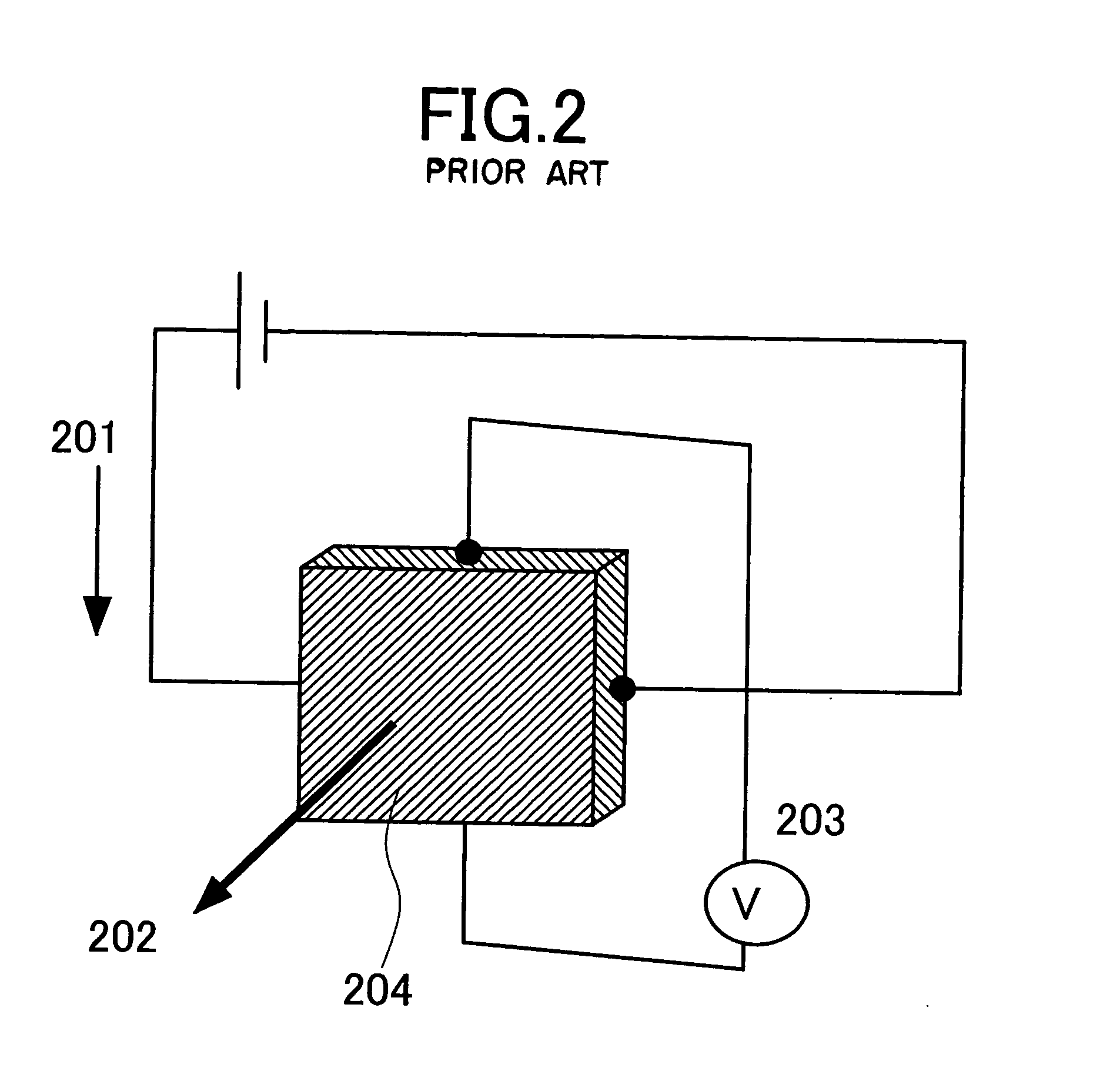
FIG. 2 is a schematic view showing a conventional thin film Hall generator, and a conventional thin film magnetic field sensor utilizing a Hall effect. FIG. 2 constitutes the magnetic field sensor which applies a phenomenon in which electromotive force is generated in a direction 203 perpendicular to both of an in-plane direction 201 and a film thickness direction 202 when a current is supplied to the direction 201 and a magnetic field is applied to the direction 202, and the magnetic field sensor measures an intensity of the magnetic filed applied to the film plane as the electromotive force. As a material constituting the thin film Hall generator, nonmagnetic semiconductors such as GaAs, InAs and InSb which offer a nature that a magnetic field and a voltage are in proportion to each other in a wide range of the magnetic field have been reported and widely put into practical use.

On the contrary, the magnetic field sensor of the present invention has a constitution, for example, a...

embodiment 2

A device of an embodiment 2 was fabricated in the following manner. Specifically, more than two devices having the structure of FIG. 3 or FIG. 4, each having the same shape and the same size, are disposed so that output terminals thereof are arranged in series and at least one current introduction terminal allows a current to flow in a direction inverse to those of other current introduction terminals.

FIG. 8 shows an example of the device of the embodiment 2, and is a principle diagram of the magnetic field sensor in which the two magnetic field sensors having the same structure, the same size and the same shape as those of FIG. 3 are arranged, the output terminals (301) in plane are arranged in series, and the current terminals (302) are arranged so that the current 802 flows in series in film thickness directions opposite to each other. A material of a sensor film is the same as that described in the embodiment 1. Moreover, in terms of the device structure, one terminal of the c...

embodiment 3

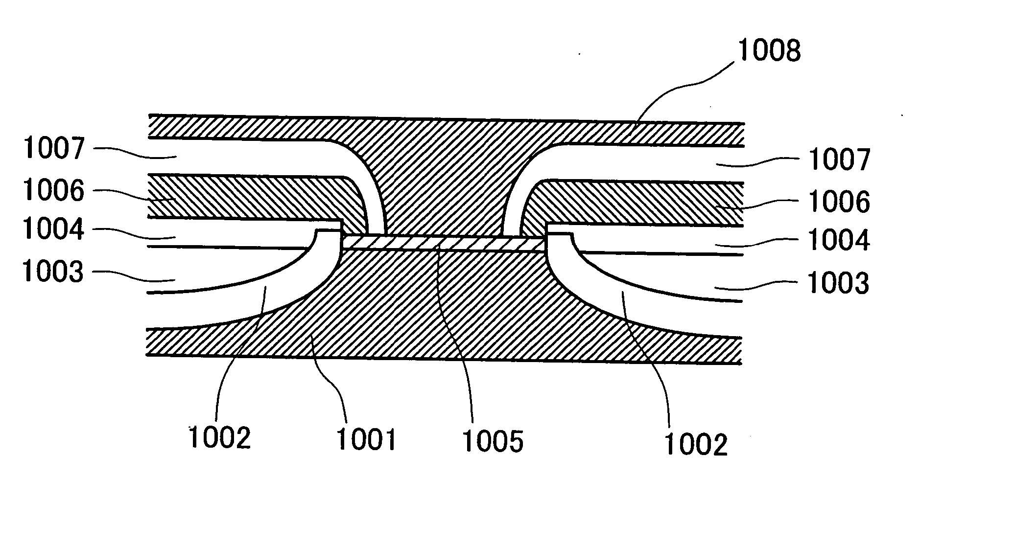
A case where the magnetic field sensor of the present invention is applied to a magnetic reading head will be described. A film containing ferromagnetic which causes an anomalous Hall effect used for the magnetic field sensor has, for example, a film structure as shown in FIG. 6, and has a structure described in the embodiment 1. A film thickness is set to an appropriate value ranging from 1 to 100 nm for the sake of an application of the magnetic field sensor to the reading head and for the sake of a practical output. In the case of this embodiment, a film having a thickness of 15 nm was used. Without depending on whether a structure, in which a sensor called an in-gap type is sandwiched between shields, is a head structure having a shape exposed to a plane opposite to the medium or a head structure in which a sensor called a yoke structure is not exposed and the sensor is disposed inside the yoke formed of C-character shaped soft magnetic, the magnetic reading head structure usin...


PUM

PropertyMeasurementUnit
magneticaaaaaaaaaa
Hall effectaaaaaaaaaa
magnetic fieldaaaaaaaaaa

Abstract

A magnetic field sensor for sensing an applied magnetic field by utilizing a Hall effect. Used, as a sensor portion, are compound materials such as FeN showing a significant anomalous Hall effect, and materials containing magnetic properties such as a magnetic semiconductor having a zincblende structure and oxide having a perovskite structure. A device structure of the magnetic field sensor is adopted, in which by providing a current terminal to a film and a voltage terminal thereof respectively in a film thickness direction and in an in-plane direction, the magnetic field can be guided into the in-plane direction.

Description

BACKGROUND OF THE INVENTION The present invention relates to a magnetic sensor for sensing magnetic fields and a magnetic reading head for reproducing information recorded onto a magnetic disc, and particularly to a magnetic sensor and a magnetic reading head, which offer excellent reproduction and resolution. DESCRIPTIONS OF THE RELATED ARTS Magnetic recording / reproduction apparatuses have made remarkable improvements in their recording densities. Magnetic recording / reproduction heads thereof have been required to possess high performance in terms of both recording and reproduction characteristics. Concerning reproduction devices, improvements of three technical points have been demanded: (1) an improvement in a high sensitivity technique, (2) an improvement in a narrowing technique of a track width, and (3) an improvement in a narrowing technique of a reproduction gap. As to the point (1), the high sensitivity of the reproduction device has been advanced by improving a MR head u...

Claims


Application Information

Patent Timeline
Patent Type & Authority Applications(United States)
IPC IPC(8): G01R33/07G01R33/09G11B5/37G11C11/18H01F10/16H01L21/8246H01L27/105H01L43/04H01L43/06H01L43/10
CPCB82Y25/00G11C11/18G11B5/374G01R33/093
Inventor TAKAHASHI, HIROMASA
Owner HITACHI LTD
Why Eureka
Try Eureka